|
|

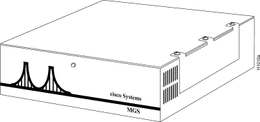
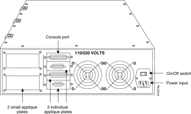
The MGS chassis is a modular chassis incorporating a four-slot Multibus backplane, which can support up to three network interface cards and one processor card. External connections to the network are provided by interface appliques attached to the rear of the chassis. These appliques are connected internally to the appropriate interface card by way of ribbon cables. Figure 1-1 shows the front of the MGS chassis, and Figure 1-2 shows the MGS rear panel and appliques.
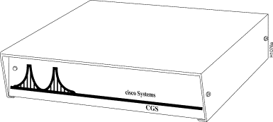
The C chassis is a modular chassis incorporating a two-slot Multibus backplane, which can accommodate up to two separate processor and interface cards. The required presence of the processor card leaves one slot that can be used for a Multibus interface card in the C chassis. There are two models: the CGS router and the CPT protocol translator. Figure 1-3 shows the front of the CGS chassis. Except for the product name, the CPT chassis front panel is identical to the CGS chassis.
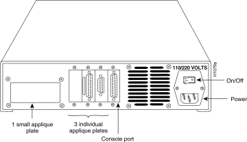
The CGS chassis can support a single multiport Ethernet, serial, or Token Ring interface card for external network connection. External connections to the network are provided by interface appliques attached to the rear of the chassis. These appliques are connected internally to the appropriate interface card by way of ribbon cables. Figure 1-4 shows the CGS rear panel and appliques.
Note The CGS chassis supports only the CSC-2R dual-port Token Ring interface card; it will not support a single-port Token Ring interface card.
The CPT chassis can support a single multiport Ethernet or serial interface card for external network connection. The CPT chassis can only support one Ethernet interface port, but it will support up to two serial interfaces.
External connections to the network are provided by interface appliques attached to the rear of the CPT. These appliques are connected internally to the appropriate interface card by way of ribbon cables. Figure 1-5 shows the CPT rear panel and appliques.
Your responsibilities for bringing the MGS or C chassis on line will include installing the chassis (only the MGS can be installed in a rack), making external connections to various networks by way of appropriate interface cables, and using the configuration software routines specified in the appropriate getting started guide.
This publication applies to hardware installation only; it will take you through the installation up to, but not including, the configuration software routines.
The different models of the MGS and C chassis are identified by their size, card and interface capacity, configuration, physical characteristics, and specifications. These specific physical characteristics and specifications are noted in the following four tables.
Table 1-1 provides a summary of the physical specifications for the MGS chassis, and Table 1-2 describes the power and cooling specifications for the MGS chassis.
Table 1-1 MGS Chassis Physical Specifications
|
Table 1-2 MGS Chassis Power and Cooling Specifications
|
|
1 cfm = Cubic feet per minute. 2 dBa = Decibels, A-weighted. |
Table 1-3 and Table 1-4 provide the specifications for the C chassis.
Table 1-3 C Chassis Physical Specifications
|
Table 1-4 C Chassis Power and Cooling Specifications
|
|
1 cfm = cubic feet per minute. 2 dBa = Decibels, A-weighted. |
This section provides an overview of the following cards that can be used in the MGS and C chassis:
The processor card is the supervisor that contains and executes most of the programs that control the system. Table 1-5 lists the specifications for the central processing unit (CPU) cards that can be used in the MGS and C chassis.
Table 1-5 Processor Card Specifications
Memory cards provide long-term, nonvolatile random-access memory (NVRAM) storage for configuration and data. Table 1-6 lists the memory cards available for the MGS and C chassis.
Table 1-6 Memory Card Specifications
|
| 1 The CSC-1R and CSC-2R cards work with the MGS chassis, but the CGS chassis can use the CSC-2R card only. |
Network interface cards connect the chassis to one or more networks. Table 1-7 describes the various network interface cards available for the MGS and C chassis and gives the chassis limitations for Token Ring interface cards.
Table 1-7 Network Interface Card Specifications
MGS only—Single-port Token Ring interface card.
MGS, CGS only—Dual-port Token Ring interface card.
Up to 2 Ethernet and 2 synchronous serial interface ports.
MGS only—Single-port Token Ring interface card.
CSC-SCI2
4 synchronous serial interface ports.
2 Cannot be used in the CPT chassis. Note The CPT can have a maximum of two serial interfaces: 2S or 2T,
where S refers to normal-speed serial lines (up to 64 kilobits per second [kbps]) and T refers to high-
speed (T1) serial lines (up to 4 kilobits per second [kbps]).
The following sections discuss the card and port limitations for the MGS and C chassis models.
Table 1-8 provides a list of the card and port types (and the quantities of each) that can be installed in the MGS and CGS chassis.
Table 1-8 Card and Port Limits for the MGS and CGS Chassis
21
CSC-SCI-4S or 4T2
2 Because only one interface card can be used in the CGS chassis, the CSC-SCI card is not typically used because it provides no NVRAM-card connector, which accommodates a NVRAM card.
The CPT chassis can support only one Ethernet interface, but it will support up to two serial interfaces. Token Ring interfaces cannot be used in the CPT chassis. The types and number of interface cards that can be used in the CPT chassis are listed in Table 1-9. The ports attach to the network by way of rear-panel appliques.
Ethernet and serial
Card and Port Limits for the CPT Chassis
External network connections to the MGS and C chassis are provided through a variety of rear-panel connector plates and appliques. Table 1-10 lists the available connector plates, their relative sizes, the maximum number of appliques per plate, and where the appliques can be positioned on the rear panel of the MGS or C chassis. Plates are listed from left to right when facing the rear panel of the MGS or C chassis. (See Figure 1-2, Figure 1-4, and Figure 1-5.)
Table 1-10 MGS and C Chassis Connector Plates
Token Ring1
22
Ethernet3
24
2 Only two Token Ring or Ethernet interfaces can be used due to slot limitations.
3 The CPT chassis can only support one Ethernet interface port, but will support up to two serial interfaces.
4 Because of its size, the RS-449 serial interface can only be used on the small plate area; therefore, only two RS-449 interfaces can be used in the C chassis.
Interface Card
Description
4- or 16-Mbps rate is user-selectable by way of software.
4- or 16-Mbps rate for each port is user-selectable by way of software.
Transmission rates up to 4 Mbps for serial and 10 Mbps for Ethernet.
Serial ports configurable as DCE or DTE1, Ethernet as Version 1 or 2.
4- or 16-Mbps rate is user-selectable by way of a jumper.
Transmission rates up to 4 Mbps for each port.
Ports can be configured as DCE or DTE.
1 DCE = Data communications equipment. DTE = Data terminal equipment.
Card and Port Limitations
MGS and CGS Card and Port Limitations
Maximum
No. of Ports
Maximum
No. of Cards
Card Type
Interface/Port Type
MGS
CGS
MGS
CGS
1 Because of its size, the RS-449 serial interface can only be used on the small plate area; therefore, only two RS-449 interfaces can be used in the CGS chassis.
CPT Card and Port Limitations
Card Type
Interface/Port Type
Maximum
No. of Ports
Maximum
No. of Cards
(any type of serial)1
1 Because of its size, the RS-449 serial interface can only be used on the small plate area; therefore, only two RS-449 interfaces can be used in the CPT chassis.
Rear Panel Configurations
MGS Chassis
C Chassis
Connectors
Small Plate 1
Small Plate 2
Individual
Plates
Small Plate
Individual
Plates
1 The CPT chassis does not support Token Ring interfaces. The CGS chassis supports only the CSC-2R dual-port Token Ring interface card, while the MGS chassis supports the CSC-1R, CSC-2R, and CSC-R16M Token Ring interface cards.
![]()
![]()
![]()
![]()
![]()
![]()
![]()
![]()
Posted: Thu Nov 6 15:55:04 PST 2003
All contents are Copyright © 1992--2003 Cisco Systems, Inc. All rights reserved.
Important Notices and Privacy Statement.