|
|

This appendix discusses products that are no longer shipping as new from the factory, but that are still supported in the field. Some of these products can be used in some MGS and C chassis platforms and some are discontinued versions of M and C chassis platforms; however, their use is either no longer recommended, or an improved version exists.
The CSC/2 processor card contains a 12.5-MHz MC68020 microprocessor, 1 megabyte (MB) of dynamic random-access memory (RAM), and supports 2 MB of read-only memory (ROM). The CSC/2 has three LEDs to indicate its operational state. Figure F-1 shows the CSC/2 card viewed from the component side. The CSC/2 card is obsolete, but still supported in the field.
Looking at the front edge of the CSC/2 card, the red LED on the left is a software-programmable status light, and it is lit during initialization, flashes or stays lit if there is an error, and is off under normal conditions. The red LED in the middle is the processor halt light, and it is on whenever the processor is in a halt state. The green LED on the right is the software-programmable run light, and it is lit when the system is running.
Most of the functions of the CSC/2 configuration register are similar to those of the CSC/3 processor card.
The CSC/2 card has configurable jumpers that control critical memory functions for the different sizes of erasable programmable read-only memories (EPROMs) that can be installed. These jumpers are changed only when the EPROM memory sizes are changed. Do not change these jumpers from their default settings unless you are instructed to do so when the software is changed. The EPROM jumper settings for the CSC/2 card are shown in Figure F-2.
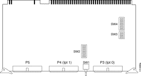
The CSC-P is a parallel printer interface card capable of controlling up to two parallel printers. The CSC-P card is obsolete, but still supported in the field. Figure F-3 shows the component-side view of the CSC-P card.
The maximum number of CSC-P cards that can be used in the M chassis is one. (The card cannot be used in the C chassis.) The placement of the CSC-P card in the chassis backplane is critical for correct operation. There must also be a CSC-MT card in the system to provide shared Multibus memory for the CSC-P card. Ensure that the CSC-MT card is in the top slot of the chassis and that the processor card is installed in the second slot. Install the CSC-P card below the processor card.
The CSC-P contains several switchable startup options listed in Table F-1.
Table F-1 CSC-P Switch Settings
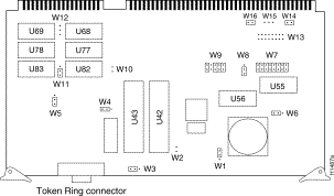
The CSC-R Token Ring interface card, shown in Figure F-4, provides interconnection to IEEE-802.5 and IBM Token Ring media. The implementation is based on the TI-TMS380 chipset and an Intel 80186 controller. The data rate for this media is a maximum of 4 megabits per second (Mbps) and is fully compatible with the IEEE 802.5 standard. The CSC-R card cannot be used in the C chassis. The CSC-R card is obsolete, but still supported in the field.
The maximum number of CSC-R cards that can be used in the M chassis is one. (The card cannot be used in the C chassis.) There must also be a CSC-MT card in the system to provide shared Multibus memory for the CSC-R card.
The CSC-R card acts as a system bus master in the chassis. Install the CSC-R card below the processor and the CSC-MT cards. The CSC-MT must be in the top slot in the chassis, and the processor card must be in the second slot.
When shipped, the CSC-R card is configured as card number 0. (See Table F-2.) Because only one the CSC-R card can be used in the M chassis, leave these jumpers in the factory-default positions.
Table F-2 CSC-R Jumper W9 Default Settings for Card Numbering
The V.35 DTE applique LED functions are listed in Table F-3, and the pinout is listed in Table F-4. There are no user configurable jumpers on the applique, and it can be used as DTE only at all of the data speeds supported by the MCI and SCI Multibus serial interface cards. There are no software or microcode-related limitations with this applique. The V.35 DTE applique is obsolete, but still supported in the field.
Table F-3 V.35 DTE Applique LED Indicators
Table F-4 V.35 DTE Applique Pinout
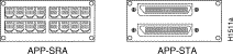
The MSM is an M chassis-based terminal server, providing a maximum of one LAN or WAN interface connection. Any single interface is valid (CSC-1E, CSC-R16M, CSC-1R, CSC-1S, or CSC-1T cards can all be used), using Ethernet or Token Ring for the LAN connection or any serial interface (RS-232, HD V.35, and so forth) for the WAN connection. The MSM chassis provides rear panel connections for up to 32 asynchronous serial connections requiring up to two CSC-16 16-line asynchronous serial cards. The available asynchronous appliques are the APP-SRA and APP-STA (see Figure F-5), and both are mounted on small plates. The APP-SRA provides 16 RJ-11 connectors, and the APP-STA provides 16 telco champ connectors.
Up to 2 of each asynchronous applique can be used for a total of 32 asynchronous-terminal connections. If 32 asynchronous terminal connections are used, the LAN or WAN interface has to be installed on one of the individual plates on the chassis rear panel, excluding the larger RS-449 interface. If an RS-449 interface is desired, only 16 asynchronous serial lines (one CSC-16 with one APP-SRA or APP-STA) can be used because the RS-449 applique must be installed in one of the small plate areas. (The RS-449 applique cannot be installed in the individual plate areas.)
The MSM chassis uses the same MAS-28 power supply and fans as the MGS chassis. (The MSM chassis used in the United Kingdom, uses the MAS-26 power supply.) The MSM chassis is obsolete, but still supported in the field.
The MTR/3 is an M chassis-based combination communication server and router that uses the CSC/3 processor card. This chassis allows a maximum of one LAN and one WAN interface, or two LAN interfaces, or two WAN interfaces. Ethernet or Token Ring interfaces can be used for the LAN connection and any serial interface (RS-232, HD V.35, and so forth) can be used for the WAN connection.
The MTR/3 chassis provides rear-panel connections for 16 asynchronous terminal connections requiring one CSC-16, 16-line asynchronous-serial card. The asynchronous applique that can be used is the APP-SRA or APP-STA. (See Figure F-5.) Both types are mounted on a small plate. The APP-SRA provides 16 RJ-11 connectors and the APP-STA provides 16 telco connectors. The MTR/3 chassis uses the same MAS-28 power supply and fans as the MGS chassis. (The MTR/3 chassis used in the United Kingdom uses the MAS-26 power supply.) The MTR/3 chassis is obsolete, but still supported in the field.
The CSC-16 asynchronous-serial card is not obsolete and is discussed in detail in the ASM-CS Hardware Installation and Maintenance publication; however, because this card is also used in the obsolete MSM and MTR/3 chassis, it is mentioned here for convenience. The CSC-16 card (also called the communication server serial line card) is a 16-port asynchronous serial interface card.
(See Figure F-6.) It is the primary card in the MSM and MTR/3 chassis.
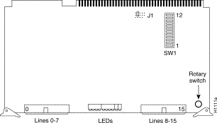
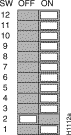
The switch SW1 controls selection of the system bus memory unit number. SW1-2 should be on, and SW1-1 and SW1-3 through SW1-8 should be off. Figure F-7 shows the SW1 default switch settings for the CSC-16 card.
Table F-5 lists the settings for SW1-9 through SW1-12, which are optional. These settings determine the unique card numbers up to the maximum number of two CSC-16 cards. The default setting is card number 0.
Table F-5 CSC-16 SW1 Optional Switch Settings
|
| 1 Figure F-7 shows this card number setting. |
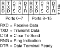
The CSC-16 contains ten LEDs that display the line states of two asynchronous serial ports (one port on for each half of the bank of LEDs). Near the right front edge of the card (when viewing the card cage front) is a 10-position rotary switch that can be operated with a small flat-blade screwdriver. At one end of the screwdriver slot is a pointer. This pointer identifies which pair of ports is being monitored in the LED display. The LEDs display the line state in the order shown in Figure F-8. (The orientation of LEDs is from left to right when viewing the front edge of the card.)
The position of the rotary switch determines which pair of ports are monitored (for example, 0 and 8 or 1 and 9). The default position of the switch as shipped is set to position to 0, and will display the signals for ports 0 and 8. The ports shown in each half of the display are selected according to Table F-6.
Table F-6 CSC-16 Rotary Switch Descriptions
![]()
![]()
![]()
![]()
![]()
![]()
![]()
![]()
Posted: Thu Nov 6 15:55:27 PST 2003
All contents are Copyright © 1992--2003 Cisco Systems, Inc. All rights reserved.
Important Notices and Privacy Statement.