|
|

Cisco Systems protocol translators support the use of X.25 as a transport mechanism for Internet packets. Cisco Systems servers use X.25 for transferring raw data over X.25 networks. In addition, the protocol translator supports X.29-based PAD connections. Refer to the X.25 Recommendation, published by the International Telegraph and Telephone Consultative (CCITT). The following information is provided in this chapter:
Cisco protocol translators have an option that allows connection to an X.25 Public Data Network (PDN). Like Cisco routers, this X.25 connection allows transport of the TCP/IP packets across the X.25 packet switching network.
Cisco routers do not support an X.25 PAD function, so they are unable to communicate with hosts directly connected to the X.25 PDN. The routers encapsulate TCP/IP packets in X.25 packets for transfer over a packet switching network. These packets can be received by Cisco routers, TRouters, terminal servers, or other Cisco protocol translators. Only Cisco's protocol translators include packet assembler/disassembler (PAD) capabilities.
The connection to the packet switching network is through a synchronous line.
To connect to an X.25 host on a PDN, a Cisco protocol translator can be used. Other systems communicate with a protocol translator using the Telnet or LAT protocols. The protocol translator can translate this into X.25, which then would be able to communicate with the X.25 host. The protocol translators support all PAD functions (X.28, X.29, and X.3).
The encapsulation subcommand of the interface configuration command sets up X.25 processing with default parameters on a serial interface. The command syntax is:
encapsulation encapsulation-typeThis subcommand takes one argument, encapsulation-type, which specifies the type of X.25 support (commercial or DDN) and whether the connection is DTE (Data Terminal Equipment) or DCE (Data Communications Equipment). DDN X.25, a variant of X.25 with automatic Internet-to-X.121 address conversion, is used primarily to pass Internet traffic on the Defense Data Network. Most connections to X.25 switches are DTE. Refer to the chapter "Configuring the System" for more a list of serial encapsulations supported with the protocol translator.
The following configuration commands set up a DTE connection to a commercial X.25 network on a serial interface:
interface serial 0
encapsulation x25
To adjust the Level 2 (LAPB) parameters of an X.25 interface, use the lapb subcommand of the interface configuration command.
The Cisco protocol translator software provides subcommands to configure the standard Level 2 and Level 3 X.25 parameters and user facilities.
This section discuses the commands and procedures needed to set these parameters including interface addresses, virtual circuit channel sequences, and addresses.
X.25 Level 2, or LAPB (Link Access Procedure, Balanced), is a data encapsulation protocol that operates at Level 2 (the data link level) of the OSI reference model. LAPB specifies methods for exchanging data (in units called frames), detecting out-of-sequence or missing frames, retransmitting frames, and acknowledging frames.
LAPB parameters are set with the lapb interface subcommand. The interface must be running with either a LAPB or X.25 encapsulation method specified by the encapsulation interface subcommand. The command syntax is:
lapb parameter valueThis subcommand takes two required arguments, parameter and value.
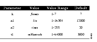
The argument parameter is one of several keywords described in the following text, and the argument value is a decimal number representing a period of time, a bit count, or a frame count, depending on parameter. Table 1-1 summarizes the LAPB parameters.
The retransmission timer determines how long a transmitted frame can remain unacknowledged before the protocol translator polls for an acknowledgment. To set the limit for the retransmission timer (the LAPB T1 parameter), use the lapb t1 subcommand. The command syntax is:
lapb t1 millisecondsThe argument milliseconds is the number of milliseconds from 1 through 64000. The default value is 3000 milliseconds.
For X.25 networks, the protocol translator retransmission timer setting should match that of the network. Mismatched retransmission timers can cause excessive retransmissions and an effective loss of bandwidth.
For leased-line circuits, the retransmission timer setting is critical. The timer setting must be large enough to permit a maximum-sized frame to complete one round trip on the link. If the timer setting is too small, the protocol translator will poll before the acknowledgment frame can return, which results in an effective loss of bandwidth. If the timer setting is too large, the protocol translator waits longer than necessary before requesting an acknowledgment, which also reduces bandwidth.
To determine an optimal value for the retransmission timer, use the privileged EXEC command ping to measure the round-trip time of a maximum-sized frame on the link. Multiply this time by a safety factor that takes into account the speed of the link, the link quality, and the distance. A typical safety factor is 1.5. Choosing a larger safety factor can result in slower data transfer if the line is noisy. However, this disadvantage is minor compared to the excessive retransmissions and effective bandwidth reduction caused by a timer setting that is too small.
To specify the maximum number of bits a frame can hold, use the lapb n1 interface subcommand:
lapb n1 bitsThe n1 keyword specifies the maximum number of bits (N1) a frame can hold. The argument bits is the number of bits from 1 through 12000, and must be a multiple of eight. The default value is 12000 bits (1500 bytes).
When connecting to an X.25 network, use the N1 parameter value set by the network administrator, which is the maximum size of an X.25 packet. When using LAPB over leased lines, the N1 parameter should be eight times the MTU.
To specify the maximum number of times an acknowledgment frame can be retransmitted, use the lapb n2 interface subcommand:
lapb n2 retriesThe argument retries is the retransmission count from 1 through 255. The default value is 20 retransmissions.
To specify the maximum permissible number of outstanding frames, called the "window size," use the lapb k interface subcommand:
lapb k window-sizeThe argument window-size is a packet count from 1 to 7. The default value is 7 packets.
The following configuration commands change the LAPB window size (the K parameter) to 3 packets:
interface serial 0
lapb k 3
To adjust the Level 3 (packet level) parameters of an X.25 interface, use the x25 subcommand of the interface configuration command.
This section describes the keywords for the x25 subcommand of the interface configuration command, used to adjust certain X.25 Level 3 parameters. These parameters must be adjusted to match the values used by the X.25 network. It is common for networks to require values different from the Cisco defaults.
To set the X.121 address of a particular network interface, use the x25 address subcommand. The address is assigned by the X.25 network:
x25 address X.121-addressThe argument X.121-address is a variable-length X.121 address.
The following configuration commands set the X.121 address for the interface:
interface serial 0
x25 address 00000123005
The value must match that assigned by the X.25 network.
To display the current X.25 parameter settings, use the EXEC command show interfaces. Refer to the "Monitoring X.25" section later in this chapter for more information.
An important part of X.25 operation is the virtual circuit channel sequence. This sequence is a range of virtual circuit channel numbers broken into four groups (listed here in numerically increasing order):
Several X.25 parameters determine the numerical ranges of the last three groups; the range for permanent virtual circuits falls numerically below the incoming call range.
X.25 communications devices use the virtual circuit channel sequence when allocating virtual circuits. When initiating a call, these devices must search for an available channel in the sequence in one of two ways. For outgoing calls (made by a DTE device), the search starts at the upper end of the outgoing call range and proceeds in the direction of decreasing channel numbers. The search continues until the device finds an available channel or reaches the lower limit of the two-way call range.
For incoming calls (handled by a DCE device), the search for channel numbers to allocate starts at the lower end of the incoming call range, and proceeds in the direction of increasing channel numbers. The search continues until the device finds an available channel or reaches the upper limit of the two-way call range. The DTE and DCE devices fail to find an available channel only if the overall sequence range is very small or when all of the channels are in use.
To set the upper and lower limit parameters of the channel ranges, use the x25 subcommand keywords listed in Table 1-2. Each keyword takes a channel number as its argument. Note that the values for these parameters must be the same on both ends of an X.25 link.
The default lower limit for all channel ranges on the protocol translator is 1; the default upper limit for all ranges is 1024. These defaults reflect a simple approach to allocating the channel ranges: assign the same low value to all lower limits, and assign the same high value to all upper limits. This approach causes the three ranges to overlap and become one large range.
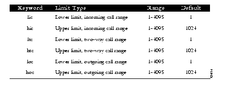
The hic keyword sets the highest incoming channel (HIC).
x25 hic channelThe argument channel is a channel number from 1 through 4095. The default value is 1024.
The hoc keyword sets the highest outgoing channel (HOC).
x25 hoc channelThe argument channel is a channel number from 1 through 4095. The default value is 1024.
The htc keyword sets the highest two-way channel (HTC).
x25 htc channelThe argument channel is a channel number from 1 through 4095. The default value is 1024.
The lic keyword sets the lowest incoming channel (LIC).
x25 lic channelThe argument channel is a channel number from 1 through 4095. The default value is 1.
The loc keyword sets the lowest outgoing channel (LOC).
x25 loc channelThe argument channel is a channel number from 1 through 4095. The default value is 1.
The ltc keyword sets the lowest two-way channel (LTC).
x25 ltc channelThe argument channel is a channel number from 1 through 4095. The default value is 1.
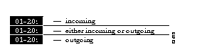
These commands set the following channels:
x25 hic 20
x25 htc 20
x25 hoc 20
Table 1-3 illustrates the effect on channels 01 through 20 of the commands in the preceding example.
The protocol translator can clear a Switched Virtual Circuit (SVC) after a set period of inactivity. To set this period, use the x25 idle interface subcommand. The command syntax is:
x25 idle minutesThe argument minutes is the number of minutes in the period. The default value is 0 (zero), which causes the protocol translator to keep the SVC open indefinitely. Both calls originated and terminated by the protocol translator are cleared.
To clear all virtual circuits at once, use the privileged EXEC command clear x25-vc. This command takes an interface type keyword (usually serial) and a unit number as arguments to identify the interface with which the virtual circuits are associated.
To clear a particular virtual circuit, the clear x25-vc command takes the two arguments described above and a logical circuit number (LCN) value as a third argument to specify the circuit.
To increase throughput across networks, you can establish up to eight switched virtual circuits to a host. To specify the maximum number of switched virtual circuits that can be open simultaneously to one host, use the x25 nvc interface subcommand:
x25 nvc countThe argument count is a circuit count from 1 to 8; the default is 1.
Upon receiving a Clear Request for an outstanding Call Request, the X.25 support code immediately tries another Call Request, if it has more traffic to send. This can overrun some X.25 switches. To prevent this problem, use the x25 hold-vc-timer configuration command:
x25 hold-vc-timer minutesThe argument minutes is the number of minutes it takes to prevent calls to a previously failed destination. Incoming calls will still be accepted.
The X.25 Level 3 retransmission timers determine how long the protocol translator must wait before retransmitting various Call Request packets. You can set these timers independently using the x25 subcommand keywords listed in Table 1-4. Each keyword requires a time value in seconds as its argument. The last column shows the default timer values, in seconds. Four of the timers apply to DTE devices, and the other four apply to DCE devices.
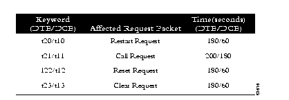
The t20 sets the limit for the Restart Request retransmission timer (T20) on DTE devices.
x25 t20 secondsThe argument seconds is a time value in seconds. The default is 180 seconds.
The t10 keyword sets the limit for the Restart Request retransmission timer (T10) on DCE devices.
x25 t10 secondsThe argument seconds is a time value in seconds. The default value is 60 seconds.
The t21 keyword sets the limit for the Call Request retransmission timer (T21) on DTE devices.
x25 t21 secondsThe argument seconds is a time value in seconds. The default value is 200 seconds.
The t11 keyword sets the limit for the Call Request retransmission timer (T11) on DCE devices.
x25 t11 secondsThe argument seconds is a time value in seconds. The default value is 180 seconds.
The t22 keyword sets the limit for the Reset Request retransmission timer (T22) on DTE devices.
x25 t22 secondsThe argument seconds is a time value in seconds. The default value is 180 seconds.
The t12 keyword sets the limit for the Reset Request retransmission timer (T12) on DCE devices.
x25 t12 secondsThe argument seconds is a time value in seconds. The default value is 60 seconds.
The t23 keyword sets the limit for the Clear Request retransmission timer (T23) on DTE devices.
x25 t23 secondsThe argument seconds is a time value in seconds. The default value is 180 seconds.
The t13 keyword sets the limit for the Clear Request retransmission timer (T13) on DCE devices.
x25 t13 secondsThe argument seconds is a time value in seconds. The default value is 60 seconds.
X.25 networks use maximum input and output packet sizes set by the network administration. You can set the protocol translator input and output packet sizes to match those of the network with the x25 subcommand keywords ips and ops, respectively:
x25 ips bytesThe argument bytes is a byte count in the range of 128 through 4096. The default value is 128 bytes.
Larger packet sizes are better, because smaller packets require more overhead processing.
To send a packet larger than the X.25 packet size over an X.25 virtual circuit, a protocol translator must break the packet into two or more X.25 packets with the M-bit ("more data" bit) set. The receiving device collects all packets with the M-bit set and reassembles them.
X.25 supports flow control with a sliding window sequence count. The window counter restarts at zero upon reaching the upper limit, which is called the window modulus. To set the window modulus, use the x25 modulo interface subcommand:
x25 modulo modulusThe argument modulus is either 8 or 128. The default value is 8. The value of the modulo parameter must agree with that of the device on the other end of the X.25 link.
To specify upper limits on the number of outstanding unacknowledged packets, use the x25 subcommand keywords win (for input window) and wout (for output window):
x25 win packetsThe argument packets is a packets count. The packet count for win and wout can range from 1 to the window modulus. The default value is 2 packets.
The x25 win determines how many packets the protocol translator can receive before sending an X.25 acknowledgment; the number is one less than win. The wout limit determines how many sent packets can remain unacknowledged before the protocol translator uses a hold queue. To maintain high bandwidth utilization, assign these limits the largest number that the network allows.
You can instruct the protocol translator to send acknowledgment packets when it is not busy sending other packets, even if the number of input packets has not reached the win count. This approach improves line responsiveness at the expense of bandwidth. To enable this option, use the x25 th subcommand:
x25 th delayThe argument delay must be between 0 (zero) and the input window size. A value of 1 sends one Receiver Ready acknowledgment per packet at all times. The default value is 0 (zero), which disables the delayed acknowledgment strategy.
The protocol translator sends acknowledgment packets when the number of input packets reaches the count you specify, providing there are no other packets to send. For example, if you specify a count of 1, the protocol translator can send an acknowledgment per input packet.
This section describes the x25 keywords for setting the X.25 Level 3 Facilities.
To set the default protocol, use the x25 default interface subcommands:
x25 default protocolThe default keyword specifies the protocol assumed by the protocol translator to interpret incoming calls with unknown Call User Data. The argument protocol is one of the following keywords:
There is no initial default value. If you do not use the x25 default subcommand, the protocol translator clears any incoming calls with unknown Call User Data.
If you use this subcommand, the protocol translator assumes that these calls use the specifies protocol.
Use the no x25 default subcommand to remove the protocol specified.
This subcommand is used when an incoming call is received without identifying CALL USER DATA. Normally, the call is cleared when this subcommand is used; the incoming call is assumed to contain the specified default protocol.
To omit the calling address in outgoing calls, use the x25 suppress-calling-address interface subcommands:
x25 suppress-calling-addressThe suppress-calling-address keyword omits the calling (source) X.121 address in Call Request packets. This option is required for networks that expect only subaddresses in the calling address field. The calling address is sent by default.
Use the no x25 suppress-calling-address subcommand to reset this subcommand to the default state.
To instruct the protocol translator to accept all reverse charge calls, use the x25 accept-reverse interface subcommands:
x25 accept-reverseThe accept-reverse keyword causes the interface to accept reverse charge calls by default. This behavior can also be configured on a per-peer basis using the x25 map subcommand:
The no form disables this facility.
To force a packet-level restart when the link level is restarted, use the x25 linkrestart interface subcommand:
x25 linkrestartThe linkrestart keyword restarts X.25 Level 2 (LAPB) when errors occur. This behavior is the default and is necessary for networks that expect this behavior. The no option disables this facility.
To set the packet network carrier, use the following interface subcommand:
x25 rpoa name numberThe x25 rpoa interface subcommand specifies a list of transit Recognized Private Operating Agencies (RPOAs) to use, referenced by name. The argument name must be unique with respect to all other RPOA names. It is used in the x25 facility and x25 map interface subcommands. The argument number is a number that is used to describe an RPOA.
To override interface settings on a per-call basis, use the x25 facility interface subcommand:
x25 facility parameter valueThe facility keyword enables X.25 facilities, which are sent between DTE and DCE devices to negotiate certain link parameters.
The arguments parameter and value specify one of the following:
To enable the or disable the ability to open a new virtual circuit based on the IP Type of Service (TOS) field, use the x25 ip-precedence interface subcommand.
[no] x25 ip-precedenceThe no x25 ip-precedence option disables the ability to open a new virtual circuit based on the IP Type (TOS) field. By default, Cisco protocol translators open one virtual circuit for each type of service.
To omit the called address in outgoing calls, use the x25 suppress-called-address interface subcommands:
x25 suppress-called-addressThe suppress-called-address keyword omits the called (destination) X.121 address in Call Request packets. This option is required for networks that expect only subaddresses in the called address field. The called address is sent by default.
Use the no x25 suppress-called-address subcommand to reset this subcommand to the default state.
To define the number of packets to be held until a virtual circuit is established, use the x25 hold-queue interface subcommand:
x25 hold-queue queue-sizeThe argument queue-size defines the number of packets. By default, this number is zero. Use the no x25 hold-queue command without an argument to remove this command from the configuration file; enter the command with a value of zero to return to the default.
The Cisco Systems protocol translators can use three methods to map Internet addresses to X.121 addresses used by X.25.
A protocol translator set up for DDN service uses the dynamic mapping technique specified in Appendix A of the DDN X.25 Host Interface Specification, available from the DDN Network Information Center (NIC). This technique has two severe limitations: it applies only to Class A Internet addresses, and it ignores the third octet of the Internet address; this technique works well for the DDN, but not for any other network.
You can establish the X.121 address of a particular network interface using the x25 address subcommand of the interface configuration command. If you do not specify the address, the protocol translator uses the DDN mapping technique to obtain the X.121 address of an interface.This command is described earlier in this chapter in the "Setting the X.25 Level 3 Parameters" section.
You can set up the Internet-to-X.121 address mapping for the host using the x25 map subcommand of the interface configuration command. Because no defined protocol can dynamically determine such mappings, you must enter a mapping for each host with which the protocol translator will exchange traffic. The command syntax is as follows:
[no] x25 map protocol-keyword protocol-address X.121-address [option1 ... [option]For the protocol translator, the argument protocol-keyword can be only be ip. The address arguments specify the network-protocol-to-X.121 mapping.
The option arguments add certain features to the mapping specified, and can be any of the following, up to six. (They must be specified in the order listed).
You can define a static host-name-to-address mapping in the host cache using the x25 host subcommand. The command syntax is:
x25 host name 121-address [cud call-user-data]The argument name is the host name.
The keyword cud call-user-data sets the call user data field in the X.25 call request packet. This keyword is optional
Protocol translator software makes it possible to limit access to the protocol translator from certain X.25 hosts using X.29 access lists. An access list can contain any number of access-list items. These are processed in the order in which they are entered, with the first match with a regular expression causing the permit|deny value of the item to be returned. If an X.121 address does not match any of the regular expressions in the access list, access will be denied.
To define an item in an X.29 access list, use the x29 access-list configuration command. The command syntax is:
x29 access-list number permit|deny regular-expressionThe argument number is the number of the access list. This can be between 1 and 99. It should be noted that the number does not determine the type of access lists, as it does in the access-list configuration command.
The keyword permit allows those source X.121 addresses matching the regular expression to access the CPT.
The keyword deny allows users to specify that their call requests clear immediately.
The argument regular expression is a regular expression similar to those used in the translate command (addressed in the "Configuring Translation" chapter). Various pattern matching constructions are available that will allow many addresses to be matched by a single regular expression. Refer to the "Pattern Matching" appendix for more information.
The no x29 access-list command deletes an entire access list. There is no way to delete a specific item from an X.29 access list.
The VTY's on a CPT can be configured with an incoming access-class using the access-list configuration command. But first use the line command as follows:
line vty 0 99Then use the access-class command as follows:
access-class number inThe argument number is the number of the access list. This can be between 1 and 99.
This access list number is used for both incoming TCP access and for incoming PAD access. In the case of TCP access, the CPT uses the IP access list defined using the access-list command. For incoming PAD connections, the same numbered X.29 access-list is referenced. If you actually only want to have access restrictions on one of the protocols, then you can create an access list that permits all addresses for the other protocol.
Each translate subcommand can be configured with an access list number. In the case of translation sessions that result from incoming PAD connections, the corresponding X.29 access list is used.
The following list shows sample commands for configuring a protocol translator interface to run X.25:
interface serial 0
address 192.31.7.50 255.255.255.240
encapsulation DDNX25
x25 win 6
x25 wout 6
x25 ips 1024
x25 ops 1024
x25 t20 10
x25 t21 10
x25 t22 10
x25 t23 10
x25 nvc 2
x25 map IP 192.31.7.49 000000010300 BROADCAST
A PAD is a packet assembler/disassembler, which is a device that collects data from a group of terminals and periodically outputs the data in packets (data organized in a special format). A PAD also does the reverse. It can take data packets from a host and return them into a character stream that can be transmitted to the terminals. A PAD is defined by CCITT Recommendations X.3, X.28, and X.29.
For a discussion and sample scenarios of one-step and two-step connections using PAD and Telnet, refer to the "Protocol Translation Methods" section in the "Using the Protocol Translator" chapter.
CCITT Recommendation X.3 specifies the parameters for terminal-handling functions such as baud rate, flow control, character echoing, and so on, for a connection to an X.25 host. The X.3 parameters are similar in function to the Telnet options.
CCITT Recommendation X.29 specifies a protocol for setting the X.3 parameters via a network connection. When a connection is established, the destination host can request that the PAD or terminal change its parameters using the X.29 protocol. A PAD can refuse to do this, in which case a terminal user can change the parameter later. A PAD cannot tell the destination host to change its X.3 parameters, but it can communicate that its own parameters were changed.
Along with Recommendations X.3 and X.29, the CCITT also sets forth Recommendation X.28 to specify the user interface for locally controlling a PAD; however, the CPT is not a PAD and this Recommendation is not supported.
You use the pad command to initiate outgoing connections to a PAD host. The pad command supports one-word connections; you are not required to enter the word "pad." The command syntax is as follows:
pad x121-address [/cud text] [/debug] [/reverse]The argument X121-address is the X.121 address of the X.25 host. If the host-to-address mapping has been set with the x25 host command, you can use the host name instead of the address.
The optional keyword /cud text is a switch that includes text in the Call User Data field of the outgoing Call Request Packet.
The optional keyword /debug is a switch that causes the informational level of logging messages to be printed whenever the remote host changes an X.3 parameter setting or sends any other X.29 control packet.
The optional keyword /reverse is a switch that causes Reverse Charge calls to be accepted on a per-call, rather than a per-interface, basis.
To connect to PAD host address 77630, enter this command:
pad 77630The X.3 parameters are normally set by the host system; however, there are occasions when the PAD is connected as a front end for some other computer or device that is not configured to set these parameters. To accommodate such systems, an X.29 READ PARAMETER message is sent immediately after opening the connection.
If the connection is made to a PAD, a PARAMETER INDICATION message is returned, and the CPT X.3 parameters are set to match those required by the PAD. If the connection is made to a host, the READ request is ignored and an X.29 SET PARAMETER message is sent. If a host sends both a PARAMETER INDICATION and X.29 SET PARAMETER message, the X.29 SET PARAMETER message takes precedence.
You use the standard escape sequence to return to the CPT EXEC. Multiple outgoing PAD connections are supported.
You use the resume command to resume a connection. The resume command also has a feature for setting X.3 PAD parameters, as explained in the subsection "Setting X.3 PAD Parameters" later in this chapter.
You can have any number of PAD connections at a time and you can switch back and forth among them. To switch from one connection to another, first type the escape sequence (Ctrl-^, X by default) to return to the EXEC. Then use the pad command to make the new connection.
Use the where command (described in the "Using the Protocol Translator" chapter) to check the logical name or number of a connection. Use the resume command to return to a previous connection.
Once you have the connection number from the where command, use the resume command and the connection number to resume the connection. The command syntax is:
resume [connection] [/keyword] [/set parameter:value]
This command also has a feature for setting X.3 PAD parameters, as explained in the subsection "Setting X.3 PAD Parameters." Local X.3 parameters may be changed during a connection by escaping back to the EXEC and issuing the resume command with the appropriate parameter set.
The optional argument connection is a connection name or number; the default is the most recently used connection.
The optional /keyword specifies line options for the connection, and can be one of the following:
The set switch is described in the next section.
You may change local X.3 parameters during a connection by using either the resume command or the x3 command.
To reset the outgoing connection default for local echo mode, enter this command:
resume 3 /set 2:1
The /set switch sets the X.3 parameters defined by parameter number and value, separated by a colon. These parameters and their values are described in the "X.3 PAD Parameters" section. For outgoing connections, the X.3 parameters default to the following:
2:1, 3:2, 4:1, 7:4, 16:127, 17:21, 18:19
All other parameters default to 0 (zero), but may be changed using the /set switch.
For incoming PAD connections, software sends an X.29 SET PARAMETER packet to set only the following parameters:
2:0, 4:1, 7:21, 15:0
If you remain at the CPT>prompt, use the x3 command to set local PAD parameters. Parameters are set directly, without using a command switch. For example, to reset the outgoing connection default for local echo mode, enter this command:
x3 2:1
Following are descriptions of the X.3 parameters. Default values for the CPT are noted in the descriptions. The default value for any parameter not so noted is 0 (zero) for outgoing connections or not set for incoming PAD connections. For incoming PAD connections, the protocol translator sends an X.29 SET PARAMETER packet to set the noted defaults.
Since the X.3 parameters describe the user's terminal, which exists on only one side of the connection, the PAD protocols are not always symmetric.
Some of these commands require ASCII decimal values which are listed in the appendix "ASCII Character Set."
Parameter 1: Escape From Data Transfer (Not Supported)
Parameter 1 determines whether or not the CPT will be allowed to escape from data transfer mode in order to send PAD command signals. Since the Cisco EXEC uses a two-character escape sequence, and there is no way to set the escape character on a Telnet connection, this parameter is refused on translation sessions as well.
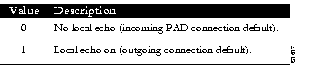
Parameter 2 determines whether or not PAD is required to perform local echo of characters. This parameter can be negotiated end-to-end on translation sessions. On incoming PAD connections, software turns local echo off on the remote PAD to support the Cisco user interface.
Parameter 3: Data Forward Character
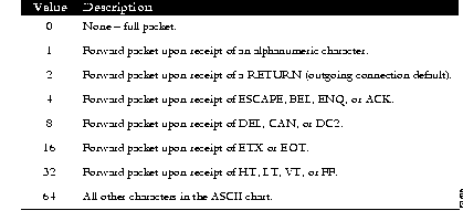
Parameter 3 sets up a packet forwarding mask, that is, it selects which character causes PAD to forward a packet either before expiration of the Idle Timer (see Parameter 4) or when in local editing mode.
As X.3 supports a wider variety of dispatch characters than Telnet does, parameter changes to or from the default causes a translation session to negotiate in or out of line mode on the Telnet connection.
A forwarding mask can be statically set using the Cisco terminal dispatch-character terminal parameter-setting command. This command can set any character or characters as the forwarding mask, and overrides (when logical) any values set by parameter 3.
Parameter 4 controls the amount of time the software waits for new data before sending a packet in the absence of a data forwarding character.
Value | Description |
|---|---|
0 | No timer. |
| 1 | Do not delay before sending a packet in the absence of a data forwarding character. This is the default. |
| 2-255 | Delay time before sending a packet, in twentieths of a second. |
Parameter 5: Device Control (Not Supported)
Parameter 5 selects whether PAD can transmit flow control (ASCII XON/XOFF) characters during data transfer to the terminal to control the terminal and data flow. Flow control is not directly supported on protocol translators because data must make network hops to travel to its final destination. However, depending on the type of incoming connection, setting this parameter may cause similar negotiations to be sent over the connection, thereby attempting to change the state of the flow control option at the device closest to the user.
Parameter 6: PAD Service Signals (Not Supported)
Parameter 6 selects whether or not PAD is required to transmit service signals. As the CPT does not use Recommendation X.28 for its user interface, this parameter is ignored.
Parameter 7: Action Upon Receipt of a Break Signal
Parameter 7 defines the action of the PAD after receiving a Break signal from the terminal.
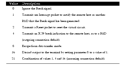
The PAD protocols allow you to send a special Indication of Break X.29 packet, send an Interrupt packet, perform a Reset operation, act as if the Recall character had been typed, or begin discarding output to the user. Combinations of these options are also allowed, as long as they make sense. Common options are to begin discarding output and send both an X.25 Interrupt packet and an X.29 Indication of Break packet, and these options are supported. All other options are not supported and are silently ignored.
Parameter 8 indicates to the PAD whether to discard received packets rather than disassemble and transmit them. This parameter works in conjunction with parameter 7. If value 16 is chosen for parameter 7, all output is discarded after reception of the Break signal. Setting parameter 8 to 0 (zero) restores normal data delivery to the terminal.
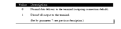
This parameter can also be set and unset manually by use of the resume command.
Parameter 9: Return Padding (Not Supported)
Parameter 9 determines whether or not PAD should provide padding (insert filler characters) upon receipt of a Return character from the terminal.
Parameter 10: Line Folding (Not Supported)
Line folding means inserting a LINE FEED at a certain point which places subsequent characters on the next line. Parameter 10 determines selection of this function and specification of the line length.
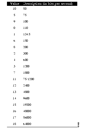
Parameter 11 is a read-only value that determines the baud rate transmitted across the interface between PAD and the terminal.
Parameter 12: Input Flow Control (Not Supported)
Parameter 12 determines whether or not the terminal can transmit ASCII XON/XOFF (transmission on and off) characters to PAD during the data transfer mode. Flow control is not directly supported on protocol translators because data must make network hops to travel to its final destination. However, depending on the type of incoming connection, setting this parameter may cause similar negotiations to be sent over the connection, thereby attempting to change the state of the flow control option at the device closest to the user.
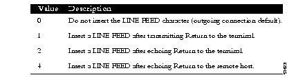
Parameter 13: LINE FEED Insertion
Parameter 13 determines the procedure for inserting the LINE FEED character upon receipt of a RETURN character. The PAD also responds to a value that results from the addition of any of the following values.
Parameter 14: LINE FEED Padding (Not Supported)
Parameter 14 determines whether or not PAD should provide padding (insert filler characters) upon receipt of a LINE FEED character from the terminal. This function is generally provided by the end user's operating system.
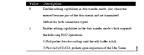
Parameter 15 enables or disables a PAD editing function for the terminal in data transfer mode. Enabling the editing function disables the Idle Timer (see Parameter 4). The user at the terminal can make corrections and display the line buffer containing the characters to be transmitted when the forwarding character (see parameter 3) is received.
Parameters 16, 17, and 18 provide the editing functions.
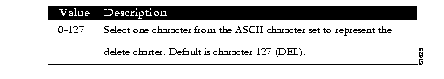
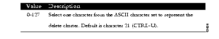
Parameter 16: Character Delete
Parameter 16 allows you to select a character that will delete characters while in PAD editing mode. This character is valid only if parameter 15 is set to 1.
Parameter 17 allows you to select a character that will delete a line while in PAD editing mode. This character is valid only if Parameter 15 is set to 1.
Parameter 18 allows you to select a character that will display a line while in PAD editing mode. This character is valid only if Parameter 15 is set to 1.

To create a profile, use the x29 profile subcommand. The command syntax is:
x29 profile name parameter:value [parameter:value]This subcommand sets up an X.3 profile for use by the translate command.
The argument name is the name assigned to the profile.
The arguments parameter and value are the X.3 PAD parameter numbers and values separated by a colon.
When an X.25 connection is established, the system acts as if an X.29 SET PARAMETER packet has been sent containing the parameters and values set by this subcommand and sets the system accordingly.
The following profile turns local edit mode on when the connection is made and establishes local echo and line termination upon receipt of a Return:
x29 profile linemode 2:1 3:2 15:1
The name linemode is used with the translate subcommand to effect use of the profile.
Refer to the "Configuring Translation" chapter for more information about the translate subcommand.
The X.3 PAD parameters are described in the "X.3 PAD Parameters" section earlier in this chapter.
To clear all virtual circuits at once, use the privileged EXEC command clear x25-vc. This command takes an interface type keyword (usually serial) and a unit number as arguments to identify the interface with which the virtual circuits are associated.
To clear a particular virtual circuit, use the clear x25-vc command. The command syntax is:
clear x25 vc interface unit [lcn]This command clears all X.25 virtual circuits at once.
The argument interface is the interface type.
The argument unit is the interface unit number.
The optional argument lcn clears the specified virtual circuit.
The protocol translator provides EXEC show commands to provide information on interface operation and virtual circuit operation. Use the EXEC command show interfaces to display interface parameters and statistics. Use the EXEC command show x25 vc to display virtual circuit parameters and statistics.
To display a mapping of Internet to X.121 addresses, use the show x25 map EXEC command. The command syntax is:
show x25 mapEach line of output shows the interface name, the Internet address, the X.121 address, and the type of mapping entry. Address-mapping types are PERMANENT (entered with the x25 map interface subcommand), INTERFACE (indicating the address of a CPT network interface), and Defense Data Network (DDN) (derived using the DDN mapping standard). If broadcasts are enabled for an address mapping, the keyword BROADCAST also appears in the output line.
If applicable, the line also shows the count of any logical channel numbers (LCNs) and a list of the LCNs for that address. An asterisk indicates the current LCN.
The following is sample command output:
Serial0: 192.31.7.49 000000010300 PERMANENT, BROADCAST, 2 LCNS: 1024, 1*
Serial0: 000000020300 INTERFACE
To display information about packet transmission and X.3 PAD parameter settings, use the show x25 pad EXEC command. The command syntax is:
show x25 padMost of the information displayed by this command will be used by an engineer to track problems.
The following is sample command output:
CPT1>show x25 pad
tty2, Incoming PAD connection
Total input: 61, control 6, bytes 129. Queued: 0 of 7 (0 bytes).
Total output: 65, control 6, bytes 696.
Flags: 1,   State: 3,   Last error: 1
 ParamsIn:  1:1, 2:0, 3:2, 4:1, 5:1, 6:0, 7:21,
    8:0, 9:0, 10:0, 11:14, 12:0, 13:0, 14:0, 15:1,
    16:127, 17:21, 18:18, 19:0, 20:0, 21:0, 22:0,
 ParamsOut:  1:1, 2:1, 3:2, 4:1, 5:0, 6:0, 7:4,
    8:0, 9:0, 10:0, 11:14, 12:0, 13:0, 14:0, 15:0,
    16:127, 17:21, 18:18, 19:0, 20:0, 21:0, 22:0,
 LCI: 1,  State: D1,  Interface: Serial0
 Started 0:11:10, last input 0:00:16, output 0:00:16
 Connected to 313700540651
 Window size input: 7, output: 7
 Packet size input: 512, output: 512
 PS: 1  PR: 5  ACK: 5  Remote PR: 1  RCNT: 0  RNR: FALSE
 Retransmits: 0  Timer (secs): 0  Reassembly (bytes): 0
 Held Fragments/Packets: 0/0
 Bytes 696/129 Packets 65/61 Resets 0/0 RNRs 0/0 REJs 0/0 INTs 0/0
Total input/output displays the number of packets received or sent for this connection. Control displays the number of packets with Qbit set (X.29 control packets). Bytes displays the number of bytes in each direction. Queued displays the number of unread packets waiting for this connection Waiting to send displays the local data packetized bit not sent (e.g. part of a line) Flags, state, last error displays data useful only to Cisco, for detecting errors and tracing initialization status ParamsIn displays the parameters read from the PAD at the start of the connection. ParamsOut displays the active X.3 parameters. LCI data displays the x25 state of the connection.
The line beginning LCI: starts a display of the status of the X.25 virtual circuit associated with this PAD connection, and is the same display seen when the show x25 vc command is executed.
To display the details of the active X.25 switched virtual circuits, use the show x25vc EXEC command. The command syntax is:
show x25 vc [lcn]The optional argument lcn is specified to examine a particular virtual circuit.
The following is sample command output:
 LCI: 1024,  State: D1,  Interface: Serial0
 Started 0:00:06, last input 0:00:06, output 0:00:06
 Connected to 31370
 Window size input: 7, output: 7
 Packet size input: 512, output: 512
 PS: 2  PR: 2  ACK: 2  Remote PR: 2  RCNT: 0  RNR: FALSE
 Retransmits: 0  Timer (secs): 0  Reassembly (bytes): 0
 Held Fragments/Packets: 0/0
 Bytes 48/10 Packets 2/2 Resets 0/0 RNRs 0/0 REJs 0/0 INTs 0/0
Some of the command output is specific to the Cisco implementation of X.25. For example, the Started field shows the number of hours, minutes, and seconds since the virtual circuit was created. A Precedent field on the third line will appear only when you have specified DDN encapsulation, and will indicate IP precedence.
On the sixth line, the PS and PR fields show the current send and receive sequence numbers, respectively. The Remote PR field shows the last number received from the other end of the circuit. The RCNT field shows the count of unacknowledged input packets. The RNR field shows the state of the Receiver Not Ready flag.
On the seventh line, the Retransmits field shows the number of times the current packet has been retransmitted. The Timer field, if non-zero, shows the current value in seconds of the LCI event timer. The Reassembly field shows the number of bytes received for a partial packet (a packet in which the M-bit is set).
On the eighth line, the Fragments part of the Held Fragments/Packets field shows the number of X.25 packets being held. (In this case, fragment refers to the X.25 fragmentation of IP data packets.) The Packets part of the Held Fragments/Packets field shows the number of IP packets currently being held pending the availability of resources, such as the establishment of the virtual circuit.
On the last line, the Bytes field shows the number of bytes sent and received. The Packets, Resets, RNRs, REJs, and INTs fields show sent and received counts for each packet type.
Use the privileged EXEC debugging commands described in this section to monitor error information about X.25 traffic. For each debug command, there is a corresponding undebug command to disable the reports.
To enable logging of LAPB (X.25 Level 2) transactions, use the debug lapb EXEC command.
To log all the X.25 circuit activities and traffic, use the debug x25 EXEC command:
To log X.25 events, use the debug x25-events EXEC command.
This command enables the monitoring of all X.25 traffic but does not display information about X.25 data or acknowledgment packets. Unlike the debug x25 command, the debug x25-events command does not report all data activity, thus reducing the volume of output.
Unlike the debug x25 command, the debug x25-events command does not report all data activity, thereby producing terse output.
The debug pad command shows debugging for all PAD connections.
To log X.25 activity on virtual circuits, use the debug x25-vc EXEC command.
This command enables logging of X.25 activity on all virtual circuits. To log this activity for a particular virtual circuit, specify an LCN by adding the optional argument lcn.
The following is a sample debug x25-vc command output:
Serial0: X25 I R1 RESTART (5) 8 lci 0 cause 7 diag 250
Serial0: X25 0 R1 RESTART CONFIRMATION (3) 8 lci 0
Serial0: X25 0 P2 CALL REQUEST (19) 8 lci 1
From(14): 31250000000101 To(14): 31109090096101
Facilities (0)
Serial0: X25 0 P6 CLEAR REQUEST (5) 8 lci 1 cause diag 122
For each event, the first field identifies the interface on which the activity occurred, and the second field indicates that it was an X.25 event. The third field indicates whether the X.25 packet was input (I) or output (O). The fourth field is the state of the interface: R1 is the normal ready state, R2 indicates the DTE not-ready state, and R3 indicates the DCE not-ready state.
The fifth field is the type of the X.25 packet that triggered the event, and the sixth field (in parentheses) gives the total length of the X.25 packet in bytes. The seventh field is the window modulus. The eighth field (labeled lci) shows the virtual circuit number. The ninth field (labeled cause) gives the cause code, and the tenth field (labeled diag) gives the diagnostic code.
For Call Request and Call Connected packets, the protocol translator shows additional information on separate lines. The From field shows the calling X.121 address and the To field shows the called X.121 address. The number in parentheses after the field name [(14)] specifies the number of digits in the address. The Facilities field indicates the length (in bytes) of the requested facilities and the facilities contents.
This section provides an alphabetical list of all the interface subcommands used in the X.25 interface:
encapsulation encapsulation-type
This subcommand takes one argument, encapsulation-type. For the purposes of an X.25 network configuration, this command specifies the type of X.25 support (commercial or DDN) and whether the connection is DTE (Data Terminal Equipment) or DCE (Data Communications Equipment). DDN X.25, a variant of X.25 with automatic Internet-to-X.121 address conversion, is used primarily to pass Internet traffic on the Defense Data Network. Most connections to X.25 switches are DTE. Refer to the "Configuring the System" chapter for a list of serial encapsulations supported.
LAPB parameters are set with the lapb interface subcommand. The interface must be running with either a LAPB or X.25 encapsulation method specified by the encapsulation interface subcommand.This subcommand takes two required arguments, parameter and value.
The argument parameter is one of several keywords described in the following text, and the argument value is a decimal number representing a period of time, a bit count, or a frame count, depending on parameter. Table 1-1 summarizes the LAPB parameters.
Specifies the maximum permissible number of outstanding frames, called the "window size."
The argument window-size is a packet count from 1 to 7. The default value is 7 packets.
Specifies the maximum number of bits a frame can hold.
The n1 keyword specifies the maximum number of bits (N1) a frame can hold. The argument bits is the number of bits from 1 through 12000, and must be a multiple of eight. The default value is 12000 bits (1500 bytes).
Specifies the maximum number of times an acknowledgment frame can be retransmitted.
The argument retries is the retransmission count from 1 through 255. The default value is 20 retransmissions.
Sets the limit for the retransmission timer (the LAPB T1 parameter), use the lapb t1 subcommand.
The argument milliseconds is the number of milliseconds from 1 through 64000. The default value is 3000 milliseconds.
Instructs the protocol translator to accept all reverse charge calls. This behavior can also be configured on a per-peer basis using the x25 map subcommand. The no variation resets the default state.
Sets the X.121 address of a particular network interface. The address is assigned by the X.25 network. The argument X.121-address is a variable-length X.121 address.
Specifies or removes the protocol assumed by the CPT to interpret calls with unknown Call User Data. The argument protocol sets the default protocol and is either ip or pad.
[no] x25 facility parameter value
Overrides interface settings on a per-call basis and enables X.25 facilities, which are sent between DTE and DCE devices to negotiate certain link parameters.
The arguments parameter and value may be as follows:
Sets the highest incoming channel (HIC). The argument channel is a channel number from 1 through 4095. The default value is 1024.
Sets the highest outgoing channel (HOC). The argument channel is a channel number from 1 through 4095. The default value is 1024.
Prevents overruns on X.25 switches for traffic through the VCs. The argument minutes is the number of minutes to prevent calls to a previously failed destination. Incoming calls will still be accepted.
[no] x25 host name 121-address [cud call-user-data]
Defines a static host-name-to-address mapping in the host cache.
The argument name is the host name.
The keyword cud call-user-data sets the call user data field in the x.25 call request packet. This keyword is optional
Sets the highest two-way channel (HTC). The argument channel is a channel number from 1 through 4095. The default value is 1024.
Sets the period of inactivity once an SVC has been cleared. The argument minutes is the number of minutes in the period. The default value is 0 (zero), which causes the protocol translator to keep the SVC open indefinitely. Both calls originated and terminated by the protocol translator are cleared.
Enables or disables the ability to open a new virtual circuit based on the IP Type of Service (TOS) field. By default, Cisco protocol translators open one virtual circuit for each type of service.
Set the protocol translator packet size to match those of the network. The ips keyword specifies the protocol translator input packet size while the keyword ops specifies the protocol translator output packet size. The argument bytes is a byte count in the range of 128 through 1024. The default value is 128 bytes. Larger packet sizes are better, because smaller packets require more overhead processing.
Sets the lowest incoming channel (LIC). The argument channel is a channel number from 1 through 4095. The default value is 1.
Forces a packet-level restart when the link level is restarted and restarts X.25 Level 2 (LAPB) when errors occur. This behavior is the default and is necessary for networks that expect this behavior. The no variation resets the default state.
Sets the lowest outgoing channel (LOC). The argument channel is a channel number from 1 through 4095. The default value is 1.
Sets the lowest two-way channel (LTC). The argument channel is a channel number from 1 through 4095. The default value is 1.
[no] x25 map protocol-keyword protocol-address X.121-address [option1 ... [option]
Specifies a network-protocol-to-X.121 address mapping from Internet-to-X.121
For the protocol translator, the argument protocol-keyword can only ip. The address arguments specify the network-protocol-to-X.121 mapping.
The option arguments add certain features to the mapping specified, and can be any of the following, up to six. (They must be specified in the order listed).
Sets the modulus. The argument modulus is either 8 or 128. The default value is 8. The value of the modulo parameter must agree with that of the device on the other end of the X.25 link.
Specifies the maximum number of switched virtual circuits that can be open simultaneously to one host. The argument count is a circuit count from 1 to 8; the default is 1.
Specifies a list of transit RPOAs to use, referenced by name. The argument name must be unique with respect to all other RPOA names. It is used in the x25 facility and x25 map interface subcommands. The argument n is a number that is used to describe an RPOA.
[no] x25 suppress-calling-address
Omits the calling (source) X.121 address in Call Request packets. This option is required for networks that expect only subaddresses in the calling address field. The calling address is sent by default. The no variation resets the default state.
Sets the limit for the Restart Request retransmission timer (T10) on DCE devices. The argument seconds is a time value in seconds. The default value is 60 seconds.
Sets the limit for the Call Request retransmission timer (T11) on DCE devices. The argument seconds is a time value in seconds. The default value is 180 seconds.
Sets the limit for the Reset Request retransmission timer (T12) on DCE devices. The argument seconds is a time value in seconds. The default value is 60 seconds.
Sets the limit for the Clear Request retransmission timer (T13) on DCE devices. The argument seconds is a time value in seconds. The default value is 60 seconds.
Sets the limit for the Restart Request retransmission timer (T20) on DTE devices. The argument seconds is a time value in seconds. The default is 180 seconds.
Sets the limit for the Call Request retransmission timer (T21) on DTE devices. The argument seconds is a time value in seconds. The default value is 200 seconds.
Sets the limit for the Reset Request retransmission timer (T22) on DTE devices. The argument seconds is a time value in seconds. The default value is 180 seconds.
Sets the limit for the Clear Request retransmission timer (T23) on DTE devices. The argument seconds is a time value in seconds. The default value is 180 seconds.
Instructs the protocol translator to send acknowledgment packets when it is not busy sending other packets, even if the number of input packets has not reached the win count, which improves line responsiveness at the expense of bandwidth.
The argument delay must be between 0 (zero) and the input window size. A value of 1 sends one Receiver Ready acknowledgment per packet at all times. The default value is 0 (zero), which disables the delayed acknowledgment strategy.
x25 win packets
x25 wout packets
Set the upper limits on the number of outstanding unacknowledged packets.
The win keyword specifies the upper limits of the number of outstanding unacknowledged packets in the input window.
The wout keyword specifies the upper limits of the number of outstanding unacknowledged packets in the output window.
The argument packets is a packets count. The packet count for win and wout can range from 1 to the window modulus. The default value is 2 packets.
[no] x29 access-list number permit|deny regular-expression
Defines an item in an X.29 access list
The argument number is the number of the access list. This can be between 1 and 99.
The keyword permit allows those source X.121 addresses matching the regular expression to access the CPT.
The keyword deny allows users to specify that their call requests clear immediately.
The argument regular expression is a regular expression similar to those used in the translate and X.25-route commands.
The no x29 access-list command deletes an entire access list.
[no] x29 profile name parameter:value [parameter:value]
Creates an X.3 profile for use by the translate command.
The argument name is the name assigned to the profile.
The arguments parameter and value are the X.3 PAD parameter numbers and values separated by a colon.
|
|