|
|

This chapter describes Cisco's Serial Tunneling (STUN) implementation. The following topics are included in this chapter:
The Cisco Serial Tunnel (STUN) function allows two devices using SDLC- or HDLC-compliant protocols that are normally connected by a direct serial link, to be connected through one or more Cisco routers. The serial frames can then be propagated over arbitrary media and topologies to another Cisco router with a STUN link to an appropriate end point. The intervening network is not restricted to STUN traffic, but rather, is multiprotocol. Instead of running parallel backbones for DECnet and SNA/SDLC traffic, for example, this traffic can now be integrated into an enterprise backbone network.
As another example, using the SDLC protocol, STUN allows networks with IBM mainframes and communications controllers to share data using Cisco routers and existing network links. As an SDLC transport function, STUN fully supports the IBM Systems Network Architecture (SNA), and allows IBM Synchronous Data Link Control (SDLC) frames to be transmitted across the network media and and/or shared serial links.
Figure 1-1 illustrates a typical network configuration with and without the Cisco SDLC transport function.
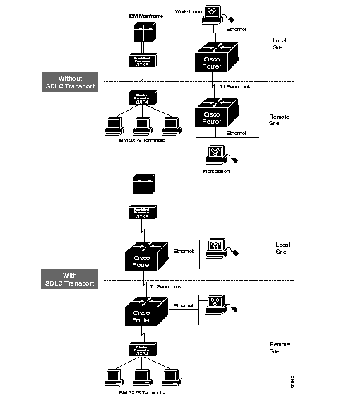
The software encapsulates SDLC frame traffic into IP packets and routes them over any of the IP-supported network media--serial, FDDI, Ethernet, and Token Ring, X.25, SMDS, and T1/T3--using the TCP transport mechanism. Because the TCP transport mechanism is used, you may use the Cisco IGRP routing protocol to route the packets. Use of IGRP allows load sharing of SDLC data for faster throughput.
As an SDLC transport, STUN copies frames to destinations based on address, but does not modify the frames in any way, or participate in SDLC windowing or retransmission; these functions are left to the communicating hosts. The STUN SDLC transport function can be treated as similar to a multidrop serial line.
The STUN function also provides for configuration of redundant links to provide transport paths in the event part of the network goes down.
Another important part of STUN's SDLC transport function is the proxy polling feature. An SDLC link is described by the type of stations connected to it, and how they are configured. The two types are point-to-point and multidrop.
In a typical configuration, a primary station, (a communications controller), manages a link that has several other stations on it called secondary stations. The stations transmit data to each other using a mode of transmission called normal response mode, whereby a secondary station can only transmit after the primary node has polled it. In networks where many secondary nodes (terminals) must be polled, this can result in traffic overloads and network bottlenecks.
The STUN proxy poll function provides a more efficient way for stations to transmit data by allowing Cisco routers to act as proxies for SDLC terminals and controllers, that is, to allow the routers to poll the secondary nodes, and then to collect and pass only significant data.
The Cisco STUN software provides several methods by which devices using HDLC-compliant protocols may exchange data via links connected to one or more Cisco routers.
One way is to use the SDLC transport feature, which behaves like a multidrop or point-to-point serial line and passes frames across arbitrary, intermediate network media unchanged, thereby expecting the host to take care of SDLC windowing and retransmission functions.
Another way is to use the serial tunneling (STUN) method, which allows you to configure arbitrary HDLC, ISO 3309-compliant frames using the TCP transport mechanism over any IP network media. Or you may define a serial transport method that propagates the tunneled frames over a serial line using a simpler, shorter encapsulation.
The software also supports configuration of redundant links, and provides commands to monitor and debug the STUN.
The following sections outline the steps you must take to configure your Cisco router for these features.These are followed by sections that describe the tasks and provide configuration examples, and the commands to maintain the links. An alphabetically arranged summary of the configuration commands is also provided at the end of the chapter.
Follow these steps to configure the SDLC transport function:
Step 1: Enable STUN and define the transport peers using the stun peer-name command.
Step 2: Specify the SDLC transport protocol using the stun protocol-group command and the sdlc keyword.
The SDLC transport uses the TCP and simple serial transport mechanisms. You assign transport peers using IP addresses or serial interface names, and transport groups by assigning group numbers and listing the protocol. Continue with these steps to configure STUN's SDLC transport on the interface:
Step 3: Configure STUN encapsulation on the interface using the encapsulation stun command.
Step 4: Specify the group in which the interface will participate using the stun group command. This step and step 3 together assign the STUN protocol to be used.
Step 5: Define how the frames will be forwarded using the stun route command.
Step 6: Configure transport-specific features such as proxy polling, if needed.
Follow these steps to configure serial tunneling:
Step 1: Enable STUN and define the transport peers using the stun peer-name command.
Step 2: Define the protocol to be used. You can choose from predefined protocols, or define your own protocol. (If you define your own protocol, this must be done before step 1 using the stun schema command.)
Step 3: Assign the predefined or new protocols to a group using the stun protocol-group command.
The STUN uses the TCP and simple serial transport mechanisms. You assign transport peers using IP addresses or serial interface names, and transport groups by assigning group numbers and listing the protocol. Continue with these steps to configure STUN on the interface:
Step 4: Configure STUN encapsulation on the interface using the encapsulation stun command.
Step 5: Specify the group in which the interface will participate using the stun group command. This step and step 4 together assign the STUN protocol to be used.
Step 6: Define how the frames will be forwarded using the stun route command.
Step 7: Configure transport-specific features such as proxy polling, if needed.
Keep the following caveats in mind when configuring STUN:
Use the stun peer-name global configuration command to enable the STUN function. The command has this syntax:
stun peer-name ip-addressEnter the IP address by which this STUN peer is known to other STUN peers that are using the TCP transport for the argument ip-address. (Even if you do not use the TCP transport, you must issue this command to define a peer name.)
Use the no stun peer-name command with the appropriate IP address to disable the STUN function.
This command assigns IP address 131.108.254.6 as the STUN peer:
stun peer-name 131.108.254.6
Each STUN interface is placed in a group which defines the ISO 3309-compliant framed protocol running on that link. Use the stun protocol-group global configuration command to define the group number and protocol. The command has this syntax:
stun protocol-group group-number protocol-keywordThe stun protocol-group command associates group numbers with protocol names. The group-number argument can be any number you select between 1 and 255. There are two predefined STUN protocols, basic and SDLC. These are specified by supplying the keyword basic or sdlc for the protocol-keyword argument. You can also define your own STUN protocol. See the section "Defining Your Own STUN Protocols" later in this chapter.
Use the no stun protocol-group command with the appropriate group number and protocol to remove an interface from the group.
The STUN SDLC transport protocol is used for placing Cisco routers in the midst of either point-to-point or multipoint (multidrop) SDLC links. At the current time, only full-duplex, NRZ-encoded links are supported. An example of how to set up the SDLC transport follows:
This example command specifies that group 7 use the SDLC STUN protocol:
stun protocol-group 7 sdlc
The basic STUN protocol is unconcerned with details of serial protocol addressing and is used when addressing is unimportant. Use this when your goal with the STUN is to replace one or more sets of point-to-point (not multidrop) serial links by using a protocol other than SDLC. An example of how to set up the basic STUN protocol follows.
This command specifies that group 5 use the basic protocol:
stun protocol-group 5 basic
To enable and configure the STUN function on a particular serial interface, use the interface subcommand. The command has this syntax:
encapsulation stunThis command must be specified. It is not possible to further configure the interface without first specifying this command.
These commands enable interface serial 0 for STUN:
interface serial0
encapsulation stun
Each STUN-enabled interface on a Cisco router must be placed in a previously defined STUN group. Packets will only travel between STUN-enabled interfaces that are in the same group. Use this interface subcommand to do this:
stun group group-numberThe argument group-number is a number you assign and which must be a decimal integer between 1 and 255 (inclusive).
These commands place serial interface 2 in STUN group 1, which is defined to run the SDLC transport:
stun protocol-group 1 sdlc
!
interface serial 2
encapsulation stun
stun group 1
To define how frames will be forwarded on the interface, use one of the following variations of the stun route interface subcommand:
stun route all tcp ip-addressUse the command forms with the all keyword when all STUN traffic received on the input interface will be propagated regardless of what address is contained in the serial frame. (These are the only stun route command forms allowed with the basic STUN transport protocol.)
The tcp keyword causes the TCP transport mechanism to be used to propagate frames that match the entry. The TCP transport allows movement of serial frames across arbitrary media types and topologies. This is particularly useful for building shared, multiprotocol enterprise network backbones. Enter the address that identifies the remote STUN peer that is connected to the far serial link for the ip-address argument.
The interface serial keywords cause the Serial Transport method of the STUN function to be used to propagate the serial frame. There must be an appropriately configured Cisco router on the other end of the designated serial line. The outgoing serial link can still be used for other kinds of traffic (the frame is not encapsulated TCP). This mode is primarily used when the complexity of the TCP transport is unjustifiable, or when higher performance is needed. Enter the serial line number connected to the Cisco router for the interface-number argument.
Use the command forms with the address keyword to specify how a serial frame that contains a particular address is to be propagated. The address you enter for the address-number argument varies with the protocol type. The argument will accept octal, decimal, or hexadecimal addresses, as appropriate, in the range allowed by the protocol. As an example, SDLC uses hexadecimal digits and has a one byte address field. The allowable addresses for this protocol must be between 00 and FF, inclusive.
It is possible to use both the all and address keywords for the same input serial interface. When this is done, the address specifications take effect first. If none of these match, the all keyword will be used to propagate the frame.
Use the command form with the direct keyword at the end of the command to indicate that the specified interface is also a direct STUN link, rather than a serial connection to another peer.
This section contains configuration examples illustrating use of the commands described in this chapter.
Figure 1-2 depicts a typical IBM network configuration.
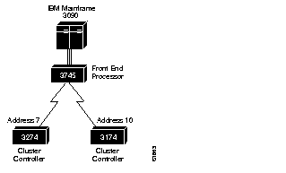
The configuration has a 3090 mainframe channel-attached to a 3745 controller, and these are connected by SDLC link to 3274 and 3174 cluster controllers.
Figure 1-3 modifies the configuration by placing Cisco routers between the devices connected via SDLC link, thus expanding the capabilities of the network. The configuration files for connecting the Cisco routers to the IBM network follow.
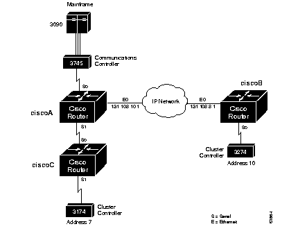
The configuration files for connecting the Cisco routers to the IBM network follow.
stun peer-name 131.108.10.1
stun protocol-group 1 sdlc
!
interface serial 0
encapsulation stun
stun group 1
stun route address 7 interface serial 1
stun route address 10 tcp 131.108.8.1
!
interface serial 1
ip address 131.108.62.1 255.255.255.0
!
interface ethernet 0
ip address 131.108.10.1 255.255.255.0
!
hostname ciscoA
router igrp 161
network 131.108.0.0
stun peer-name 131.108.8.1
stun protocol-group 1 sdlc
!
interface serial 0
encapsulation stun
stun group 1
stun route address 10 tcp 131.108.10.1
!
interface ethernet 0
ip address 131.108.8.1 255.255.255.0
!
hostname ciscoB
router igrp 161
network 131.108.0.0
stun peer-name 131.108.62.2
stun protocol-group 1 sdlc
!
interface serial 0
ip address 131.108.62.2 255.255.255.0
!
interface serial 1
encapsulation stun
stun group 1
stun route address 7 interface serial 0
hostname ciscoC
router igrp 161
network 131.108.0.0
As another example, the previous configuration can be extended by connecting a remote 3745 to another serial interface connected to ciscoB. All other traffic from the primary node (the 3745 connected to the 3090), other than addresses 7 and 10, should go to this remote 3745. Figure 1-4 illustrates this configuration.
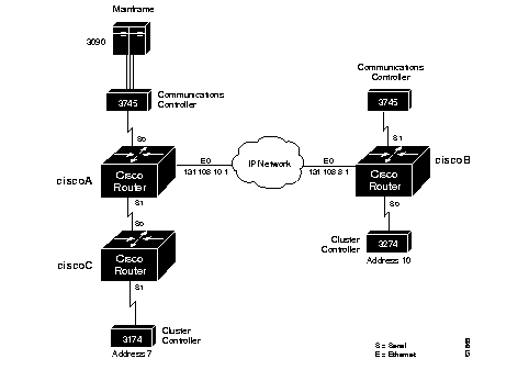
The following configuration changes would need to be made to the serial interface in the router labeled ciscoB.
interface serial 1
encapsulation stun
stun group 1
stun route all tcp 131.108.10.1
Serial 0 on ciscoA now looks like this:
interface serial 0
encapsulation stun
stun group 1
stun route address 7 interface serial 1
stun route address 10 tcp 131.108.8.1
stun route all tcp 131.108.8.1
Notice in the above examples that the same STUN group number is used in all cases. If these numbers differ between the three routers, attempts at communication will be unsuccessful. There are times, however, when having multiple groups can be useful. Such an example is illustrated in Figure 1-5.

In the following configuration, the AS/400 device labeled A wants to communicate with the 3174 device labeled A, as do the AS/400 device labeled B and 3174 device labeled B. Notice that both of the 3174 devices are at SDLC address C1. A first attempt at the configuration files for the routers labeled ciscoA and ciscoB could be as follows.
stun peer-name 131.108.1.1
stun protocol-group 1 sdlc
!
interface ethernet 0
ip address 131.108.1.1 255.255.0.0
!
interface serial 0
encapsulation stun
no ip address
no keepalive
stun group 1
stun route address C1 tcp 131.108.1.2
!
interface serial 1
encapsulation stun
no ip address
no keepalive
stun group 1
stun route address C1 tcp 131.108.1.2
stun peer-name 131.108.1.2
stun protocol-group 1 sdlc
!
interface ethernet 0
ip address 131.108.1.2 255.255.0.0
!
interface serial 0
encapsulation stun
stun group 1
stun route address C1 tcp 131.108.1.1
!
interface serial 1
encapsulation stun
stun group 1
stun route address C1 tcp 131.108.1.1
A problem occurs when the router labeled ciscoA transfers an SDLC frame with address C1 from the AS/400 A device to the router labeled ciscoB. There would be no way to determine that it came from the AS/400 device A and was therefore destined to the 3174 device A, or that it came from the AS/400 device B and was therefore destined to the 3174 device B.
The use of distinct group numbers solves this problem. The configuration shown below will ensure correct communication, as frames that come in on group 1 links will only go out of group 1 links. The same holds true for frames coming in on group 2, or any other numbered group link. The new configuration follows.
stun peer-name 131.108.1.1
stun protocol-group 1 sdlc
stun protocol-group 2 sdlc
!
interface ethernet 0
ip address 131.108.1.1 255.255.0.0
!
interface serial 0
encapsulation stun
stun group 1
stun route address C1 tcp 131.108.1.2
!
interface serial 1
encapsulation stun
no ip address
no keepalive
stun group 1
stun route address C1 tcp 131.108.1.2
stun peer-name 131.108.1.2
stun protocol-group 1 sdlc
stun protocol-group 2 sdlc
!
interface ethernet 0
ip address 131.108.1.2 255.255.0.0
!
interface serial 0
encapsulation stun
stun group 1
stun route address C1 tcp 131.108.1.1
!
interface serial 1
encapsulation stun
stun group 2
stun route address C1 tcp 131.108.1.1
At times, you may wish to prioritize STUN traffic in your network over that of other protocols. The use of priority output queuing, described in the chapter "Adjusting Interface Characteristics" enables this functionality. STUN uses a special serial line protocol called STUN for the simple serial encapsulation, and TCP port 1994 for the TCP encapsulation. Therefore, to fully specify STUN traffic on priority list 4 for high priority, the following configuration is used.
priority-list 4 stun high
priority-list 4 ip high tcp 1992
In the following sample network in Figure 1-6, there are two redundant links between the Cisco routers.
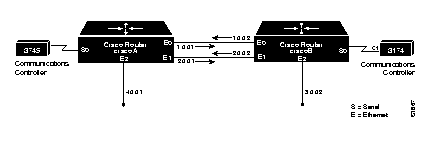
However, if you were to specify remote peers on network 1 for the two routers, the redundancy would be in effect only as long as network 1 were available. The following example shows the network configuration.
The configuration for the router labeled ciscoA is as follows:
stun peer-name 1.0.0.1
stun protocol-group 1 sdlc
interface ethernet 0
ip address 1.0.0.1 255.0.0.0
interface ethernet 1
ip address 2.0.0.1 255.0.0.0
interface ethernet 2
ip address 4.0.0.1 255.0.0.0
interface serial 0
encapsulation stun
stun group 1
stun route address C1 tcp 1.0.0.2
The configuration for the router labeled ciscoB is as follows:
stun peer-name 1.0.0.2
stun protocol-group 1 sdlc
interface ethernet 0
ip address 1.0.0.2 255.0.0.0
interface ethernet 1
ip address 2.0.0.2 255.0.0.0
interface ethernet 2
ip address 3.0.0.2 255.0.0.0
interface serial 0
encapsulation stun
stun group 1
stun route address C1 tcp 1.0.0.1
In the event that network 1 went down, then the access to network 1.0.0.1 from the router labeled ciscoB (and to network 1.0.0.2 from ciscoA) would be lost. Therefore, connectivity would be lost for the 3745 and the 3174, even though a second path exists.
When you configure redundant links, keep the following rule in mind:
In the above case, specifying the following configuration would allow connectivity between the 3745 and 3174 in all cases, when either or both network 1.0.0.0 or network 2.0.0.0 were working.
The configuration for the router labeled ciscoA is as follows:
stun peer-name 4.0.0.1
stun protocol-group 1 sdlc
interface ethernet 0
ip address 1.0.0.1 255.0.0.0
interface ethernet 1
ip address 2.0.0.1 255.0.0.0
interface ethernet 2
ip address 4.0.0.1 255.0.0.0
interface serial 0
encapsulation stun
stun group 1
stun route address C1 tcp 3.0.0.2
The configuration for the router labeled ciscoB is as follows:
stun peer-name 3.0.0.2
stun protocol-group 1 sdlc
interface ethernet 0
ip address 1.0.0.2 255.0.0.0
interface ethernet 1
ip address 2.0.0.2 255.0.0.0
interface ethernet 2
ip address 3.0.0.2 255.0.0.0
interface serial 0
encapsulation stun
stun group 1
stun route address C1 tcp 4.0.0.1
There may still be cases where such remote networks do not exist. Consider the following network illustrated in Figure 1-7:

In this situation, keep this rule in mind:
Both networks 1.0.0.0 and 2.0.0.0 in the above example would be available when the following configuration is used.
Example configuration for the router labeled ciscoA:
stun peer-name 4.0.0.1
stun protocol-group 1 sdlc
interface ethernet 0
ip address 1.0.0.1 255.0.0.0
interface ethernet 1
ip address 2.0.0.1 255.0.0.0
interface serial 0
encapsulation stun
stun group 1
ip address 4.0.0.1 255.0.0.0
stun route address C1 tcp 3.0.0.2
Example configuration for the router labeled ciscoB:
stun peer-name 3.0.0.2
stun protocol-group 1 sdlc
interface ethernet 0
ip address 1.0.0.2 255.0.0.0
interface ethernet 1
ip address 2.0.0.2 255.0.0.0
interface serial 0
encapsulation stun
stun group 1
ip address 3.0.0.2 255.0.0.0
stun route address C1 tcp 4.0.0.1
In normal communication between an SDLC primary node and its secondary node, the secondary node is only allowed to send data to the primary node in response to a poll from the primary node. In the following example, an AS/400 host is attached to a 3174 controller that handles transfers from several attached 3270 terminals:
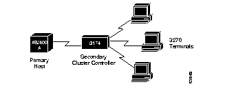
If one of the 3270-style terminals attached to the 3174 controller wants to initiate a data transfer, (usually the result of a user at the terminal pressing the Enter key), the 3174 device would not be able to immediately transfer the data back to the host AS/400 since the 3174 is the secondary node on the link. Instead, it must hold the data until a poll is received from the AS/400, which is the primary node in this example. Once the poll is received, the data can then be transmitted.
The primary host ensures a reasonable response time for its secondary nodes by sending out polls at a rate that is often more than 20 times per second. With two devices sharing a single, dedicated serial line, as in the example above, this poses no problem, as the link would be idle without the polls.
In the following example, the frequent polls and their replies would constantly travel between the two Cisco routers across the shared Ethernet.
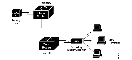
Such constant traffic can create bottlenecks and loads where they cannot be appropriately handled.
The proxy polling feature alleviates the load across the network by allowing the Cisco routers to act as proxies for the primary and secondary nodes, thus keeping polling traffic off of the shared links.
With proxy polling enabled, the router labeled ciscoA in Figure 1-9 would reply to the AS/400 poll requests, as a proxy for the secondary node, thereby keeping the polls and requests off of the shared Ethernet. Similarly, the router labeled ciscoB would act as a proxy for the primary node and periodically send polls to the secondary 3174 device, and thereby keep its replies off of the shared cable. Only significant information is passed across the shared Ethernet.
Use these interface subcommands to enable proxy polling:
stun proxy-poll address address modulus modulus {primary|secondary }Enter the address of the device on which to enable proxy polling with the address argument.
Enter the modulus of the link as defined by the MODULUS parameter specified in the line descriptions on your SDLC host with the modulus argument. (This most often will be eight.)
Use the primary or secondary keyword to indicate which role the SDLC device is playing.
Use the command form with the discovery keyword when you do not want to specify the primary and secondary ends and the modulus used on an SDLC link, or when such connections are negotiable.
Use of the discovery keyword is not recommended except where you cannot avoid end hosts that negotiate the status, since proxying will be disabled on the link until session start-up, when the appropriate primary and secondary status, as well as modulus on the link, can be discovered. Until this time, all polls travel through the network.
By default, proxy polling is disabled. Once enabled, use the no stun proxy-poll command with the appropriate arguments to return to the default state.
This command enables proxy polling for a secondary device at address C1 on interface serial 2 running with modulus 8:
interface serial 2
stun proxy-poll address C1 modulus 8 secondary
You may change the number of milliseconds between each sequence of proxy polls generated on the secondary side of a connection. Use the global configuration command stun poll-interval to do so. The command has this syntax:
stun poll-interval millisecondsThe command applies to all secondary proxy sessions in the router.
Enter the number of milliseconds desired with the milliseconds argument. The default and minimum value that can be specified is 20, or 1/50th of a second.
The no stun poll-interval command returns the default state.
This example sets the poll interval to 100 milliseconds, or 10 times per second:
stun poll-interval 100
Periodically, even when proxy polling is enabled, the router on the primary side of an SDLC connection will pass through a poll from the primary SDLC device through the network to the secondary SDLC device. This action causes the secondary device's reply to also traverse the entire network. This periodic pass-through provides an insurance mechanism that makes sure the primary SDLC device maintains an accurate notion of the secondary SDLC device status.
You can change the number of seconds between each pass through of polls between the primary and secondary SDLC devices. Use the global configuration command stun primary-pass-through to do so. The full command syntax follows.
stun primary-pass-through secondsThe stun primary-pass-through command applies to all primary proxy sessions in the router. Use the no stun primary-pass-through command to return to the default state.
This example sets the primary pass-through interval to 20 seconds.
stun primary-pass-through 20
Cisco's STUN implementation allows you to define your own STUN protocols. This step must be done before defining the protocol group using the stun protocol-group command.
This feature allows you to transport any serial protocol that meets the following criteria across a Cisco router internetwork. The following conditions must be obeyed by your serial protocol to have it transferred in this manner:
In addition, if you want to use anything but the predefined, basic protocol, which does not allow the specification and routing by an address to achieve a virtual multidrop result, your protocol must also meet the following constraints:
As an overview, SDLC frames have two formats, basic and extended. In the basic SDLC frame shown in Figure 1-10, the Address and Control fields are both 8 bits (also one byte or octet) wide. In the Extended Control format, the Control field is 16 bits wide.
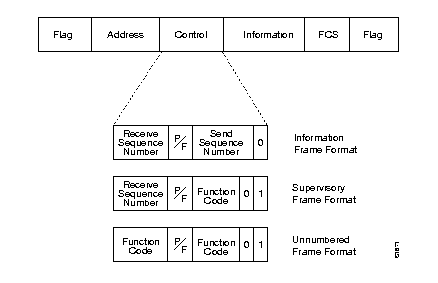
The Address field contains the address of a sending or receiving station, depending upon the procedure. The Control field contains information that determines the type of SDLC frame being transmitted, either:
The Frame Check Sequence (FCS) field is always 16 bits long. A Flag is a special bit sequence that defines the beginning and end of a frame. The bytes in the SDLC frame, except for the FCS, are always transmitted low-order bit first. The FCS bits are transmitted high-order bit first.
Use the stun schema global configuration command to specify the format, or schema, for your protocol. The command syntax follows:
stun schema name offset constant-offset length address-length format format-keywordThe argument name is a name that can be up to 20 characters in length that defines your protocol.
The argument constant-offset specifies the constant offset, in bytes, for the address to be found in the frame. The argument address-length specifies the length of that address. The length is limited and these limits are described in Table 1-1.
The argument format-keyword specifies the format to be used to specify and display addresses for routes on interfaces that use this STUN protocol. The allowable formats are listed inTable 1-1:
| Format | Allowable Base |
|---|---|
| decimal | base 10 addresses (0-9) |
| hexadecimal | base 16 addresses (0-f) |
| octal | base 8 addresses (0-7) |
The address-length argument, in bytes, is limited to the following:
| If format-keyword is: | the address-length is: |
|---|---|
| decimal | 4 |
| hexadecimal | 8 |
| octal | 4 |
The command no stun schema removes the schema.
This command defines a format of SDLC as a new STUN protocol. (This definition of SDLC would not support the proxy polling option available with the predefined protocol definition.)
stun schema new-sdlc offset 0 length 1 format hexadecimal
Once defined, new protocols may be used in the stun protocol-group interface subcommands to tie STUN groups to the new protocols.
This section describes the EXEC commands you use to monitor the state of the STUN.
Use the show stun command to examine the current status of the STUN. The command has this format:
show stunSample output is shown below:
ciscoA#show stun
This peer: 131.108.10.1
Serial0 -- 3174 Controller for test lab (group 1 [sdlc])
state  rx_pkts  tx_pkts  drops  poll
  7[ 1] IF Serial1         open     20334    86440      5  8P
 10[ 1] TCP 131.108.8.1    open      6771     7331      0
all[ 1] TCP 131.108.8.1    open    612301  2338550   1005
The first entry reports proxy polling enabled for address 7 and that Serial 0 is running with modulus 8 on the primary side of the link. The link has received 20,334 packets, transmitted 86,440 packets, and dropped 5 packets. See Table 1-2.
| Field | Descriptions |
|---|---|
| This peer | Lists the peer-name or address. The interface name (as defined by the interface description subcommand), its STUN group number, and the protocol associated with the group are shown on the header line. |
| STUN address | Address or the word "all" if the default forwarding entry is specified, followed by a repeat of the group number given for the interface. |
| Type of link | Description of link, either a serial interface using Serial Transport ("IF" followed by interface name), or a TCP connection to a remote router ("TCP" followed by IP address). |
| state | State of the link: open is the normal, working state; direct indicates a direct link to another line, as specified with the direct keyword on the stun route interface subcommand. |
| rx_pkts | Number of received packets. |
| tx_pkts | Number of transmitted packets. |
| drops | Number of packets that for whatever reason had to be dropped. |
| poll | Report of the proxy poll parameters, if any. A "P" indicates a primary and an "S" indicates a secondary node. The number before the letter is the modulus of the link. |
Use the show stun sdlc command to examine the proxy state of various interfaces on an address-by-address basis. The command has this format:
show stun sdlcSample output is shown below:
ciscoA#show stun sdlc
Serial 1 -- 3174 controller for test lab
B3: s2 C1: p4 DE: d6
This example output shows us that Serial 1 has three addresses for which proxy polling is enabled. These are B3, for which this end is a secondary link in state 2 and C1 for which this end is a primary link and in state 4. Finally, DE is in the primary/secondary/modulus discovery state 6.
The display reports the status of the interfaces using SDLC encapsulation and whether proxy polling is enabled for that interface. Interfaces with proxy polling enabled are noted with the address followed by an indication of node type, either "s" for secondary, "p" for primary or "d" for discovery, and the state of the node. Possible node states are defined in Table 1-3.
| State | Description |
|---|---|
| 0 | Significant data traveling between the primary and secondary node. No proxy polling occurring. |
| 1-3 | Proxy polling in process of being initiated. |
| 4 | Proxy polling is activated for the link at this time. If this in the primary node, the Cisco router responds to the primary's poll. If this is the secondary node, the Cisco router will periodically generate polls for potential response by the secondary. |
| 5 | The primary Cisco has data from the secondary to send to the primary SDLC machine, but is waiting for a poll from that machine before transmitting the data. |
| 6-7 | This Cisco router is still trying to determine the primary/secondary character and modulus of the SDLC hosts attached to it. No proxying is done in these states. |
The above sample reports that serial 0, while using SDLC encapsulation, is not using the proxy polling feature. Serial 0 has three address, B3, C1, and DE on which proxy polling is enabled. The address B3 is a secondary link in state 2; the address C1 is the primary link, and is in state 4; the address DE is in discovery state 6.
This section describes the privileged EXEC debugging commands you use to debug operation of the STUN. Generally, you will enter these commands during troubleshooting sessions with Cisco Customer Engineers. For each debug command, there is a corresponding undebug command to disable the reports.
debug stun-packet [group] [address]
The debug stun-packet command enables debugging of packets traveling through the STUN links. When enabled, it will produce numerous messages showing every packet travelling through the links. The optional argument group is the decimal integer assigned to a group. When the group parameter is given, output will be limited to only packets associated with STUN group specified. If the optional address argument is also specified, output will be further limited to only those packets with the STUN address specified. The address argument is in the format appropriate for the STUN protocol running for the group for which it is specified.
The debug stun command enables debugging of STUN connections and status. When enabled, it will cause messages showing connection establishment and other overall status message to be displayed.
Following are the global configuration commands used to configure the STUN function. These commands may appear anywhere in the configuration file.
[no] stun peer-name ip-address
Enables or disables STUN. The argument ip-address is the IP address by which this STUN peer is known to other STUN peers that are using the TCP transport.
[no] stun poll-interval milliseconds
Changes the interval between each sequence of proxy polls generated on the secondary side of the connection. The argument milliseconds is the interval desired, in milliseconds. Default and minimum value is 20, or 1/50th of a second, which is returned by use of the no keyword.
[no] stun primary-pass-through seconds
Changes the number of seconds between each pass through of polls between the primary and secondary SDLC devices. The argument seconds defines the interval.
[no] stun protocol-group group-number protocol
Associates or removes group numbers with protocol names. The group-number argument can be any number you select between 1 and 255. The protocol argument is any predefined protocol, or protocol defined by you.
[no] stun schema name offset constant-offset length address-length format format-keyword
Specifies or removes a format, or schema, for a user-defined protocol.
The argument name defines the protocol. The argument constant-offset specifies the constant offset, in bytes, for the address to be found in the frame. The argument address-length specifies the length of that offset. The argument format-keyword specifies the format to be used to specify and display addresses for routes on interfaces that use this STUN protocol. The allowable formats and their maximum lengths are as follows:
| Formats | Base | Length |
|---|---|---|
| decimal | base 10 addresses (0-9) | 4 |
| hexadecimal | base 16 addresses (0-f) | 8 |
| octal | base 8 addresses (0-7) | 4 |
Following are the interface subcommands used to configure STUN. These commands follow an interface command.
encapsulation stun
Enables the STUN function. This command must be specified in order to use STUN.
[no] stun group group-number
Places STUN-enabled interface in a previously defined group.
The argument group-number is user-defined and must be between 1 and 255 (decimal).
[no] stun proxy-poll address address modulus modulus {primary|secondary}
[no] stun proxy-poll address address discovery
Enable or disable proxy polling.
The address argument is the address of the device on which to enable proxy polling.
The modulus argument is the modulus of the link as defined by the MODULUS parameter specified in the line descriptions on the SDLC host.
The primary or secondary keyword indicate which role the SDLC device is playing.
The discovery keyword is used when primary and secondary ends are not specified and connections are negotiated.
Default is proxy polling disabled.
[no] stun route all tcp ip-address
[no] stun route all interface serial interface-number
[no] stun route all interface serial interface-number direct
[no] stun route address address-number tcp ip-address
[no] stun route address address-number interface serial interface-number
[no] stun route address address-number interface serial interface-number direct
Enable or disable forwarding of frames on the interface.
The all keyword is used when all STUN traffic received on the input interface will be propagated regardless of what address is contained in the SDLC frame.
The tcp keyword causes the TCP transport mechanism to be used to propagate frames that match the entry. Enter the address that identifies the remote STUN peer that is connected to the far SDLC link for the ip-address argument.
The interface serial keywords cause the Serial Transport method of the STUN function to be used to propagate the SDLC frame. There must be an appropriately configured Cisco router on the other end of the designated serial line. Enter the serial line number connected to the Cisco router for the interface-number argument.
The address keyword specifies how an SDLC frame that contains a particular address is to be propagated. The address-number argument varies with the protocol type. The argument will accept any octal, decimal, or hexadecimal address in the range allowed by the protocol.
The all and address keywords are used for the same input serial interface. When this is done, the address specifications take effect first. If none of these match, the all keyword will be used to propagate the frame.
The direct keyword is used to indicate that the specified interface is also a direct STUN link, rather than a serial connection to another peer.
|
|