|
|

This chapter provides the following procedures for installing the router at your site, installing power supplies, making all external cable connections, and applying power:
An optional rack-mount kit is available for mounting the router in a standard 19-inch-wide equipment rack with four unobstructed outer rails. This kit is suitable for use with other rack types, such as Telco-type equipment racks. If you plan to use an equipment shelf or other type of rack installation, review the guidelines in the section "Equipment Racks" in the chapter "Preparing for Installation" before proceeding. If you are not rack-mounting the router, proceed to "General Installation" later in this chapter.
 | Caution Before installing the chassis in a rack or wiring closet, read the section "Safety Recommendations" in the chapter "Preparing for Installation" to familiarize yourself with the proper site and environmental conditions. Failure to read and follow these guidelines could lead to an unsuccessful installation and possible damage to the system and components. |
The procedures for rack-mounting the router are included in the configuration note Cisco 7000 and Cisco 7507 Rack-Mount Kit Installation Instructions (Document Number 78-1058-xx, where xx is the latest version). A printed copy of this configuration note ships with the rack-mount kit and is also available on UniverCD. Follow the procedures included in this configuration note to install your Cisco 7000 in a rack. If you do not plan to rack-mount your chassis, proceed to the following section, "General Installation."
The router should already be in the area where you will install it, and your installation location should already be determined; if not, refer to the section "Site Requirements" in the chapter "Preparing for Installation."
When installing the router on a table or floor, ensure that you have planned a clean, safe location for the chassis and have considered the following:
 | Warning Two people are required to lift the chassis safely. Grasp the chassis underneath the lower edge and lift with both hands. Keep your back straight and lift with your legs, not your back. |
Step 2 On the rear of the chassis, do the following:
Step 3 Ensure that both power supply bays are empty.
 | Warning Never attempt to lift the chassis with the handles on the power supplies or on the interface processors, or by the plastic panels on the front of the chassis. These handles are not designed to support the weight of the chassis. |
Step 4 Two people are required to perform this step. With a person positioned at either side of the chassis, grasp the bottom edge of the chassis with one hand near the front and the other near the back. Together, slowly lift the chassis. Avoid sudden twists or moves to prevent injury.
Step 5 Place the router in a location where the air intake vent on the front of the chassis (the bottom front panel) is not drawing in exhaust air from other equipment.
Step 6 Ensure that you have at least three or four feet of clearance around the rear of the chassis. You will need this space to install the power supplies, perform maintenance on the chassis, and observe LEDs.
Step 7 After you correctly position the chassis, proceed to the following section, "Installing Power Supplies."
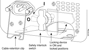
You will install one or two, AC-input or DC-input power supplies in the upper and lower power supply bays in the rear of the chassis. Always install the first power supply in the lower power supply bay and the second, if any, in the upper bay. The power supply switch is also an interlock tab. (See Figure 3-1.) When the switch is in the on (|) position, the tab extends into a slot in the chassis to prevent the power supply from being removed accidentally or from falling out of the chassis.
Before proceeding, ensure that you have sufficient working space (3 to 4 feet) behind the chassis and that access to the power supply bays is not blocked by an equipment rack power strip or cables from other equipment. If cables from other equipment are in the way, move them aside and temporarily secure them with tie wraps before proceeding. Keep in mind that cables that block access to the bays may also block the power supply LEDs from view. If a power strip or other rack fixture is in the way, you may need to loosen the chassis ears from the equipment rack-mounting strips and carefully push the chassis out of the rack until you can maneuver each power supply into a bay.
You need the following tools to complete this procedure:
Before beginning the power supply installation, note the type of the installation screws on all power supplies, and check the area around the power supply bays to determine which tools you will need.
This section describes how to proceed if your system is installed in an equipment rack, and if you do not have clear access to both power supply bays. If the chassis is not in a rack, or if you already have clear access to the power supply bays, proceed to the following section, "Inserting Power Supplies."
 | Warning This procedure shifts the chassis' center of gravity toward the front of the rack and may cause the rack or the chassis to tip. Before performing this procedure, ensure that you have sufficient help (assistants) to support the rack and the chassis to prevent them from tipping forward. |
Step 2 Check the power supply bays and ensure that access is not blocked. If it is not, proceed to the following section, "Inserting Power Supplies."
Step 3 If cables from other equipment fall in front of the power supply bay, carefully gather the cables (using care not to strain them) and use cable ties to anchor them away from the power supply bays. If no other equipment blocks access to the bay, proceed to the following section, "Inserting Power Supplies."
Step 4 If access to the power supply bays is partially blocked by a power strip or other permanent rack fixture, you will need to detach the chassis from the rack and carefully slide it forward until you can maneuver each power supply into a bay. Make sure that at least one other person is available to support the front of the chassis as you push it out the front of the rack and, if necessary, to continue to support it while you insert the power supplies.
Step 5 Use a 3/16-inch flat-blade screwdriver to loosen the four screws that secure the left and right ears to the front mounting strips on the equipment rack.
 | Warning Never attempt to lift or support the front of the chassis with the plastic front panels. The panels can break away and allow the chassis to drop. |
Step 6 Position at least one person in front of the rack to support the front underside of the chassis and prevent it from falling as it is pushed forward out of the rack. Grasp the chassis along the metal undersides behind the plastic front panels. If possible, position two people in front of the rack, one person to support each side of the chassis.
Step 7 From the rear of the equipment rack, slowly push the chassis forward out of the rack until there is enough clearance for the power supplies to be inserted into the bay.
Step 8 If the chassis is installed near the bottom of the rack, allow the bottom front edge of the chassis to rest on the floor while you install the power supplies. If the chassis is too high in the rack for this to be practical, proceed to the following section, "Inserting Power Supplies," and perform the steps as quickly as possible.
Step 9 When the power supplies are installed, push the chassis back into the rack until the ears meet the mounting strip on both sides of the equipment rack.
Step 10 Slide the chassis back into the rack until the ears meet the mounting strips on both sides of the rack.
Step 11 Secure each ear to the rack-mounting strip with two 10-32 x 3/8-inch slotted binder-head screws.
Step 12 Proceed to the section "Connecting AC and DC Power" later in this chapter.
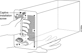
When you have clear access to the power supply bays, install the first AC-input or DC-input supply in the lower bay and the second supply, if any, in the upper bay. Each power supply weighs 20 pounds. Figure 3-2 shows the correct way to handle a power supply. Install each power supply as follows:
Step 2 Check the switch on the face of the power supply, and place it in the off (O) position. The interlock tab should not extend out of the unit.
Step 3 Hold the power supply by the handle and place your other hand underneath to support the bottom. (See Figure 3-2.)
Step 4 The power supply has casters on the bottom end. Place the casters inside the lower power supply slot and position the power supply so that it is aligned in the slot to go straight in.
 | Caution When inserting a power supply into the bay, do not use unnecessary force; slamming the power supply into the bay can damage the connectors on the rear of the supply and inside the chassis. |
Step 5 Push the power supply all the way into the bay. Do not use unnecessary force; push the supply into the bay until the power supply front panel is flush with the chassis rear panel.
Step 6 Tighten the captive installation screw on the top of the power supply. This screw prevents the power supply from shifting away from the internal connector and provides proper grounding for the supply.
 | Caution Do not turn on any power supplies until you are ready to power up the system. The interlock switch that locks the power supply in the slot also turns on the system power. |
Step 7 If you are installing only one power supply, proceed to the following section, "Connecting AC and DC Power."
Step 8 Use a number 2 Phillips or 1/4-inch flat-blade screwdriver to loosen the captive installation screw and remove the filler plate from the upper power supply bay. Save the filler plate so that you can replace it later if necessary.
Step 9 Repeat Steps 2 through 6 for the second power supply.
For optimum reliability, connect redundant power supplies to separate input lines.
Connect an AC-input power supply as follows:
Step 2 To secure the cable in the power supply AC receptacle, push the cable-retention clip up until it snaps into place around the connector. The cable-retention clip provides strain relief for the AC power cord.
Step 3 Repeat steps 1 and 2 for the second power supply, if any.
Step 4 Connect each power supply cord to a separate input line.
Step 5 To connect the external interface cables to the chassis, proceed to the following section, "Connecting Interface Cables."
Connect a DC-input power supply as follows:
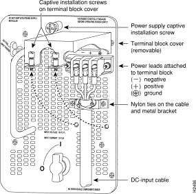
Step 2 Using a screwdriver, attach the power leads to the terminal block. (See Figure 3-3.)
The wire should be at least 8 AWG. Color code selection for the DC-input cable depends on the color code of the DC power source at your site. Typically, negative is black, positive is red or white, and ground is green. No matter which color coding is used, make certain it matches that used at the DC source for negative, positive, and ground. (See Figure 3-3.)
 | Warning Incorrectly wiring the terminal block could create a dangerous shock hazard and could damage the power supply, power source, and the Cisco 7000 chassis components. |
Step 3 To provide strain relief for the three DC-input cable, attach two nylon ties around the cable and the metal bracket. (See Figure 3-3.)
Step 4 Install the terminal block cover over the terminal block, and tighten the captive installation screws. (See Figure 3-3.) Do not overtighten the captive installation screws on the terminal block cover. The recommended torque is 8.2 ±0.4 inch-lb.
 | Warning To prevent a short-circuit or shock hazard after wiring the DC-input power supply, replace the terminal block cover. |
Step 5 Connect the opposite end of the DC-input cable to the DC power source.
If you are installing or replacing a second power supply, repeat Step 1 through Step 5 for the second power supply. Proceed to the following section, to connect the external interface cables to the chassis.
The following sections describe the basic network connections you will make to the router. Using the Configuration Worksheet will help you to make connections and later configure each interface without having to access the rear of the chassis to check port addresses. Complete the "Site Log" in the chapter "Preparing for Installation" if you have not already done so.
The following guidelines will assist you in properly connecting the external network cables to your router.
 | Warning A voltage mismatch can cause equipment damage and may pose a fire hazard. If the voltage indicated on the label is different from the power outlet voltage, do not connect the chassis to that receptacle. |
If the router fails to operate in the manner specified in software documents, refer to Chapter 4 to help isolate the problem, and then notify a customer service representative.
This sections that follow provide illustrations of the connections between the router interface ports and your network(s). Interface cables and equipment, such as Ethernet transceivers and interface cables, should already be available and in place. If they are not, refer to the section "Preparing Network Connections" in the chapter "Preparing for Installation" for descriptions of the equipment you need for each interface type to complete the connection to your network. Descriptions of network connections follow.
All AIP ATM interfaces are full-duplex. You must use the appropriate ATM interface cable to connect the AIP with an external ATM network. The AIP provides an interface to ATM switching fabrics for transmitting and receiving data up to 155 megabits per second (Mbps) bidirectionally; the actual data rate is determined by the PLIM.
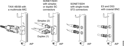
The AIP can support interfaces that connect to the following physical layers:
Connect the AIP interface cables as shown in Figure 3-4. For detailed descriptions of ATM cabling requirements, refer to the section "Distance Limitations" in the chapter "Preparing for Installation" and also the section "AIP Interface Types" in the chapter "Preparing for Installation."
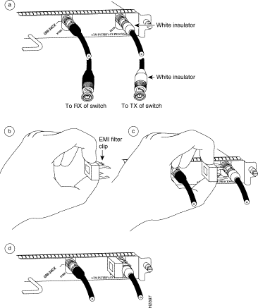
 | Caution To ensure compliance with EMI standards, the E3 PLIM connection requires an EMI filter clip (CLIP-E3-EMI) on the receive port (RCVR); the DS3 PLIM connection does not require this clip. Figure 3-5 shows the EMI filter clip assembly that is required for the E3 PLIM. Do not operate the E3 PLIM without this assembly. |
The E3 and DS3 PLIMs require cable CAB-ATM-DS3/E3. If you have an E3 PLIM, you must follow steps 1 through 3 to install the CAB-ATM-DS3/E3 cable and EMI filter assembly. If you do not have an E3 PLIM, proceed to the appropriate section for your configuration.
One portion of the cable has a white insulator on both ends to ensure that the receive-to-transmit and transmit-to-receive relationship is maintained between the E3 PLIM and your ATM switch. The portion of the cable with the white insulator should attach between receive and transmit or transmit and receive ports of the E3 PLIM and your ATM switch, respectively.
Step 2 Hold the EMI filter clip as shown in Figure 3-5b and attach it to the receive cable as shown in Figure 3-5c.
Step 3 To ensure that the clip is not pulled off when adjacent interface processors are removed, position the clip parallel to the orientation of the AIP. (See Figure 3-5d.)
Connecting bus and tag or Enterprise System Connection (ESCON) cables between the CIP and a host processor is beyond the scope of this publication. The specific CIP connection requirements are discussed in detail in the configuration note Channel Interface Processor (CIP) Installation and Configuration (Document Number 78-1342-xx, where xx is the latest version of the document). This configuration note ships with the CIP and is available on UniverCD.
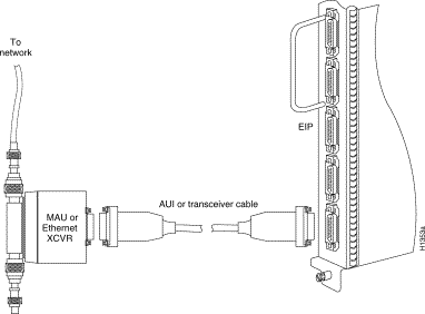
An Ethernet transceiver or MAU should already be connected to your network. Connect each Ethernet port on the EIP to an Ethernet transceiver with a transceiver cable, or to an attachment unit with an attachment unit interface (AUI). Figure 3-6 shows an example of a typical connection. Some transceivers connect directly to the Ethernet port on the EIP (usually the 10BASE-T type) and do not require an interface cable. On each EIP port, slide the metal bracket up over two posts on the cable connector, or tighten the thumbscrews to secure the cable in the port and provide strain relief. For descriptions of the connection equipment and connector locks, refer to the section "Ethernet Connection Equipment" in the chapter "Preparing for Installation."
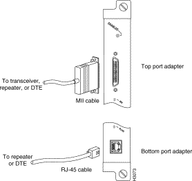
For an MII connection, a 100BaseT transceiver or MAU should already be connected to your network. The RJ-45 connection does not require an external transceiver.
On a single 100BaseT port adapter, you can use either the RJ-45 connection or the MII connection. If you have two 100BaseT port adapters on your FEIP, you can use the RJ-45 connection on one and the MII connection on the other.
If you have RJ-45 connections, attach the Category 5 UTP cable directly to the RJ-45 port on the FEIP. (See Figure 3-7.)
If you have MII connections, attach an MII cable directly to the MII port on the FEIP or attach a 100BaseT or 100BaseF transceiver, with the media appropriate to your application, to the MII port on the FEIP. (See Figure 3-7.)
Attach the network end of your RJ-45 or MII cable to your 100BaseT or 100BaseF transceiver, switch, hub, repeater, DTE, or whatever external, 100BaseT equipment you have.
 | Caution To prevent problems on your FEIP and network, do not simultaneously connect RJ-45 and MII cables to one 100BaseT port adapter. On a single 100BaseT port adapter, only one network connection can be used at one time. Only connect cables that comply with EIA/TIA-588 standards. |
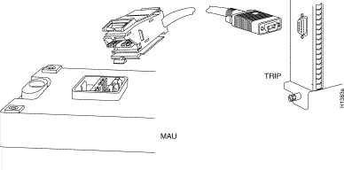
Media access unit (MAU) connectors provide a direct connection between the TRIP and the ring. Figure 3-8 shows the connections.
The speed of each Token Ring port must match the speed of the ring to which it is connected. The default speed for all TRIP ports is 4 Mbps, which you can change to 16 Mbps on any port with the configuration command ring-speed n, where n is the speed (4 or 16) in Mbps. Before you enable the Token Ring interfaces, ensure that each is set for the correct speed, or it can bring the ring down. The following sample session changes the ring speed on Token Ring port 1/2 from the default 4 Mbps to 16 Mbps:
7000# configure terminal

Enter configuration commands, one per line. End with CNTL/Z.
7000 (config)# int tokenring 1/2

7000 (config)# ring-speed 16

7000 (config)# ^Z

7000# copy running-config startup-config

[OK]
7000#
 | Caution Each TRIP port must be configured for the same ring speed as the ring to which it is connected, either 4 or 16 Mbps. If the port is set for a different speed, it will cause the ring to beacon, which effectively brings the ring down and makes it inoperable. |
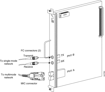
Both single-mode and multimode connections are available and can be combined on one FIP. The fiber-optic cable connects directly to the FIP ports. Single-mode uses separate transmit and receive cables. You will need two single-mode cables for a single attachment connection or four cables for a dual attachment connection. Multimode uses one integrated transmit/receive cable for each physical interface (one for PHY A and one for PHY B). You will need one multimode cable for a single attachment connection, and two cables for a dual attachment connection. Figure 3-14, which shows the connections for a dual attachment connection that uses both single-mode and multimode fiber, illustrates the types of connections used for both fiber modes. For pinout descriptions, refer to the section "FDDI Connection Equipment" in the chapter "Preparing for Installation."
This section also provides instructions for connecting an optical bypass switch to a dual attachment multimode network connection. Because the method of connecting optical bypass switches varies between different manufacturer's models, refer to the documentation for your particular bypass switch for correct connection instructions. If you are installing an optical bypass switch, proceed to the section "Installing an Optical Bypass Switch" later in this chapter.
 | Warning Invisible laser radiation may be emitted from the aperture ports of the single-mode FDDI products when no fiber cable is connected. Avoid exposure and do not stare into open apertures. This product meets the Class 1 Laser Emission Requirement from CDRH FDDI. |
A FIP that is connected as a single attachment station (SAS) typically is connected to the ring through a concentrator. The FIP receives and transmits the signal through the same physical interface, usually PHY A. Depending upon whether you are connecting to a single-mode of multimode fiber network, connect the FIP as follows:
If you are connecting other FIPs as dual attachment stations (DASs) proceed to the following section. Otherwise, proceed to the section "Connecting the Console Terminal" later in this chapter.
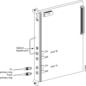
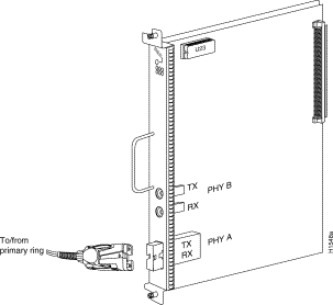
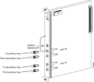
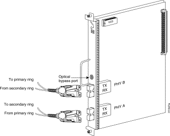
A FIP that is connected as a dual attachment station (DAS) connects to both the primary and secondary rings. The signal for each ring is received on one physical interface (PHY A or PHY B) and transmitted from the other. The standard connection scheme (which is shown in Figure 3-11) for a DAS dictates that the primary ring signal comes into the FIP on the PHY A receive port and returns to the primary ring from the PHY B transmit port. The secondary ring signal comes into the FIP on the PHY B receive port and returns to the secondary ring from the PHY A transmit port. Failure to observe this relationship will prevent the FDDI interface from initializing. Figure 3-14 shows the connections for a dual attachment that uses both multimode and single-mode fiber.
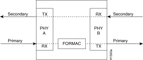
Depending on whether you are connecting to a single-mode or multimode fiber network, connect the FIP as follows:
If you are connecting an optical bypass switch, proceed to the next section. Otherwise, proceed to the section "Connecting the Console Terminal" later in this chapter.
If you are connecting an optical bypass switch, proceed to the next section. Otherwise, proceed to the section Connecting the Console Terminal later in this chapter.
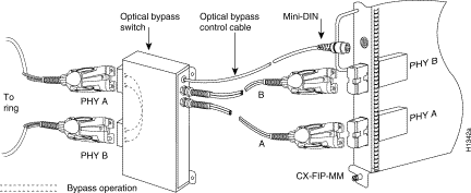
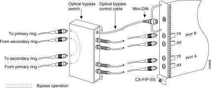
An optical bypass switch is a device installed between the ring and the station that provides additional fault tolerance to the network. If a FIP that is connected to a bypass switch fails or shuts down, the bypass switch activates automatically and allows the light signal to pass directly through it, bypassing the FIP completely. A port for connecting an optical bypass switch is provided on the multimode/multimode FIP (CX-FIP-MM) and the single-mode/single-mode FIP (CX-FIP-SS) only. (See Figure 3-15 for CX-FIP-MM connections and Figure 3-16 for CX-FIP-SS connections.)
The optical bypass control port on the FIP is a six-pin mini-DIN receptacle. Some optical bypass switches use DIN connectors, and some use a mini-DIN. A DIN-to-mini-DIN control cable (CAB-FMDD) is included with the FIP to connect optical bypass switches that use the larger DIN connector. Up to 100 milliamperes of current can be supplied to the optical bypass switch.
Following are general instructions for connecting an optical bypass switch to the FIP; however, your particular bypass switch may require a different connection scheme. Use these steps as a general guideline, but refer to the instructions provided by the manufacturer of the switch for specific connection requirements.
All FSIP ports support any available interface type and mode. The serial adapter cable determines the electrical interface type and mode of the port to which it is connected. EIA/TIA-232, EIA/TIA-449, V.35, and X.21 interfaces are available in DTE mode with a plug at the network end and in DCE mode with a receptacle at the network end. EIA-530 is available only in DTE mode with a plug. For descriptions and illustrations of each connector type, refer to the section "Serial Connection Equipment" in the chapter "Preparing for Installation." For cable pinouts, refer to the appendix "Cabling Specifications."
When connecting serial devices, consider the adapter cables as an extension of the router for external connections; therefore, use DTE cables to connect the router to remote DCE devices such as modems or data service units (DSUs), and use DCE cables to connect the router to remote DTE devices such as a host, PC, or another router. (See Figure 3-17.) The optional or additional connection equipment required depends on the interface type of each port.
A pair of metric thumbscrews is included with each port adapter cable. If you plan to connect to a remote device that uses metric hardware, replace the standard 4-40 thumbscrews at the network end of the port adapter cable with the M3 metric thumbscrews.
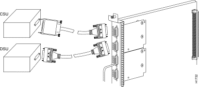
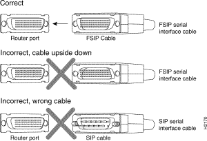
 | Caution The SIP and FSIP each use unique interface cables that are not interchangeable. Attempting to force a SIP cable (which uses DB-15 or DB-25 plugs) into the FSIP universal, 60-pin receptacle can damage the FSIP. (See Figure 3-18.) |
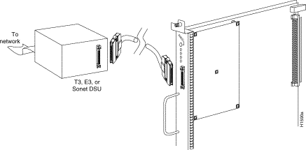
The HIP HSSI port functions as a DTE when it is connected to a DSU for a standard HSSI connection, and it can also be connected to a collocated router with a null modem cable. To connect the router to a HSSI network, use a HSSI interface cable between the HIP port and the DSU. Both ends of the HSSI interface cable are the same, so you can connect either end to the HIP or DSU. (See Figure 3-19.)
To connect two routers back to back in order to verify the operation of the HSSI port or to build a larger node, use a null modem cable between available HSSI ports in two separate routers. (See Figure 3-20.) The two routers must be in the same location, and can be two Cisco 7000s, two AGS+ routers, or one of each. When you configure the ports, you must enable the internal transmit clock on in the HSSI interface in both routers with the command hssi internal-clock. To negate the command when you disconnect the cable, use the command no hssi internal-clock. For complete command descriptions and instructions, refer to the related software documentation.

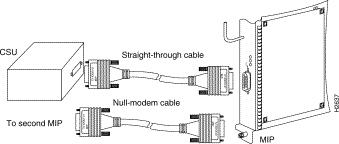
Two standard T1 serial cables are available from Cisco Systems and other vendors for use with the MIP: null-modem and straight-through. These interface cables are used to connect your router to external CSUs. The cables have male 15-pin DB connectors at each end to connect the MIP with the external CSU.
Connect the T1 cable as shown in Figure 3-21.
The system console port on the RP (or RSP7000) is a DCE DB-25 receptacle for connecting a data terminal, which you will need to configure and communicate with your system. The port is located on the RP (or RSP7000) below the auxiliary port and is labeled Console. (See Figure 3-22.)
Before connecting the console port, check your terminal's documentation to determine the baud rate of the terminal you will be using. The baud rate of the terminal must match the default baud rate (9600 baud). Set up the terminal as follows:
Use the console cable provided to connect the terminal to the console port on the RP (or RSP7000), then follow the steps in the section "Starting the Router" later in this chapter.
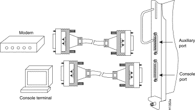
The auxiliary port is a DB-25 plug DTE port for connecting a modem or other DCE device (such as a CSU/DSU or other router) to the router. The port is located on the RP (or RSP7000) above the console port and is labeled Auxiliary. An example of a modem connection is shown in Figure 3-22.
When all interfaces are connected, perform a final check of all connections, then power up the system as follows:
Step 2 Check the external power connections; the power-supply switches should still be OFF.
Step 3 Check the console terminal and make sure it is ON.
Step 4 When you have checked all of the connection points in Steps 1 through 3, turn the lower power supply on by turning the power supply switch clockwise one-quarter turn. The AC power LED on the power supply and the lower power LED on the front of the chassis will light.
Step 5 After the lower power supply is on, turn on the upper power supply, if one is present, for redundant power. The AC power LED on the power supply and the upper power LED on the front of the chassis will light.
Step 6 Listen for the system blower. It generates about 60 dBa, so you should immediately hear it start operating.
Step 7 While the system initializes, the yellow boot error LED on the RP lights for about 5 seconds or less, then goes out when the boot is complete. If this LED stays on longer than 10 seconds, or if it lights after system initialization, a boot error has occurred. Refer to the chapter "Troubleshooting the Installation" for troubleshooting procedures.
Step 8 During the boot process, the LEDs on most of the interfaces light in irregular sequence. Some may light and remain on, go out, and light again for a short time. Some will stay on during the entire boot process if an interface is already configured and brought up (such as the EIP receive LED, which lights steadily as it detects traffic on the line). Wait until the system boot is complete before attempting to verify the interface processor LED indications.
Step 9 When the system boot is complete (a few seconds), the RP begins to initialize the interface processors. During this initialization, the LEDs on each interface processor behave differently (most flash on and off). The enabled LED on each interface processor lights when initialization has been completed, and the console screen displays a script and system banner similar to the following:
GS Software (GS7), Version 10.3(1)
Copyright (c) 1986-1995 by Cisco Systems, Inc.
Compiled Wed 15-Mar-95 11:06
Your installation is complete. Proceed to the appropriate software publications to configure your interfaces. If the system does not complete each of these steps, proceed to the chapter "Troubleshooting the Installation" for troubleshooting procedures.
Many of the interface processor LEDs will not light until you have configured the interfaces. In order to verify correct operation of each interface, complete the first-time startup procedures and configuration, then refer to the LED descriptions in the appendix "Reading LED Indicators" to check the status of the interfaces.
This section describes installation, removal, and typical operations of the 8- or 16-MB, Intel Series 2+ Flash memory card, which installs in the PCMCIA slot on the RP (or RSP7000) faceplate.
The Flash memory card is used to store and boot Cisco Internetwork Operating System (Cisco IOS) software images and interface processor microcode images, and can be used as a server to store software and microcode images for other systems.
The spare Flash memory card is shipped blank; you must format it before using it. (Formatting instructions are included in this document.) The Flash memory card shipped with a spare RP or shipped with a system is already formatted.
Note that the following sections are in a chronological order typical of many Flash memory card installations: inserting the card, formatting the card, copying an image to the card, and making that image bootable.
Note that the following sections are in a chronological order typical of many Flash memory card installations: inserting the card, formatting the card, copying an image to the card, and making that image bootable.
The Flash memory card can be inserted and removed with the power on. Following is the procedure for installing and removing a Flash memory card:
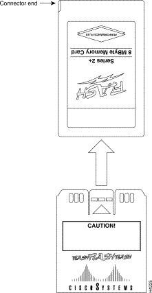
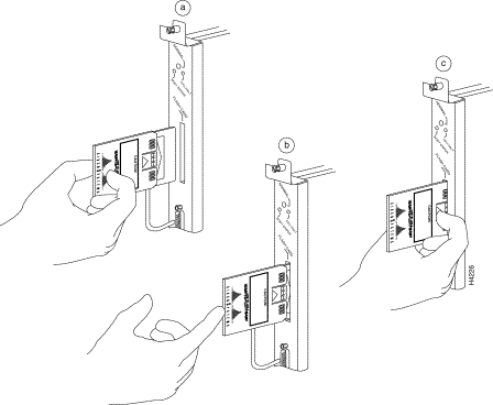
Step 2 Hold the Flash memory card with the connector end of the card toward the PCMCIA slot. The product label should face to the right, as shown in a of Figure 3-24.
Step 3 Insert the card into the slot until the card completely seats in the connector at the back of the slot. Note that the card does not insert all the way inside the RP (or RSP7000); a portion of the card and sleeve remains outside of the slot. Do not attempt to force the card past this point. The Flash memory card is keyed and cannot be seated the wrong way.
Step 4 To remove the card, grasp the card near the slot and squeeze the sleeve together to release it from the slot. Then pull the card free from the connector at the back of the slot. (See c in Figure 3-24.)
Step 5 Place the removed Flash memory card on an antistatic surface or in a static shielding bag.
 | Caution The formatting procedure erases all information on the Flash memory card. To prevent the loss of important data that might be stored on a Flash memory card, proceed carefully. If you want to save the data on a Flash memory card, copy the data to a server before you format the card. |
Use the following procedure to format a new Flash memory card:
Step 2 To format the Flash memory card, use the format slot0 command as follows. (Use only Intel Series 2+ Flash memory cards.)
Router# format slot0:

All sectors will be erased, proceed? [confirm]
Enter volume id (up to 30 characters): MyNewCard

Formatting sector 1
Format device slot0 completed
Router#
The new Flash memory card is now formatted and ready to use.
With the Flash memory card formatted, you can now copy an image into it. To copy an image, use the following procedure, which assumes the following:
Following is the procedure for copying a bootable file (called new.image) into the Flash memory card:
Step 2 To enable the router, copy the image new.image to the Flash memory card using the following series of commands:
Router> en

Password:
Router# copy tftp:new.image slot0:new.image

20575008 bytes available on device slot0, proceed? [confirm]
Address or name of remote host [1.1.1.1]?
Loading new.image from 1.1.1.1 (via Ethernet1/0): !!!!!!!!!!!!!!!!!!!!!!!!!!!!!!
!!!!!!!!!!!!!!!!!!!!!!!!!!!!!!!!!!!!!!!!!!!!!!!!!!!!!!!!!!!!!!!!!!!!!!!!!!!!!!!!
!!!!!!!!!!!!!!!!!!!!!!!!!!!!!!!!!!!!!!!!!!!!!!!!!!!!!!!!!!!!!!!!!!!!!!!!!!!!!!!!
!!!!!!!!!!!!!!!!!!!!!!!!!!!!!!!!!!!!!!!!!!!!!!!!!!!!!!!!!!!!!!!!!!!!!!!!!!!!!!!!
!!!!!!!!!!!!!!!!!!!!!!!!!!!!!!!!!!!!!!!!!!!!!!!!!!!!!!!!!!!!!!!!!!!!!!!!!!!!!!!!
!!!!!!!!!!!!!!!!!!!!!!!!!!!!!!!!!!!!!!!!!!!!!!!!!!!!!!!!!!!!!!!!!!!!!!!!!!!!!!!!
!!!!!!!!!!!!!!!!!!!!!!!!!!!!!!!!!!!!!!!!!!!!!!!!!!!!!!!!!!!!!!!!!!!!!!!!!!!!!!!!
!!!!!!!!!!!!!!!!!!!!!!!!!!!!!!!!!!!!!!!!!!!!!!!!!!!!!!!!!!!!!!!!!!!!!!!!!!!!!!!!
!!!!!!!!!!!!!!!!!!!!!!!!!!!!!!!!!!!!!!!!!!!!!!!!!!!!!!!!!!!!!!!!!!!!!!!!!!!!!!!!
!!!!!!!!!!!!!!!!!!!!!!!!!!!!!!!!!!!!!!!!!!!!!!!!!!!!!!!!!!!!!!!!!!!!!!!!!!!!!!!!
!!!!!!!!!!!!!!!!!!!!!!!!!!!!!!!!!!!!!!!!!!!!!!!!!!!!!!!!!!!!!!!!!!!!!!!!!!!!!!!!
!!!!!!!!!!!!!!!!!!!!!!!!!!!!!!!!!!!!!!!!!!!!!!!!!!!!!!!!!!!!!!!!!!!!!!!!!!!!!!!!
!!!!!!!!!!!!!!!!!!!!!!!!!!!!!!!!!!!!!!!!!!!!!!!!!!!!!!!!!!!!!!!!!!!!!!!!!!!!!!!!
!!!!!!!!!!!!!!!!!!!!!!!!!!!!!!!!!!!!!!!!!!!!!!!!!!!!!!!!!!!!!!!!!!!!!!!!!!!!!!!!
!!!!!!!!!!!!!!!!!!!!!!!!!!!!!!!!!!!!!!!!!!!!!!!!!!!!!!!!!!!!!!!!!!!!!!!!!!!!!!!!
!!!!!!!!!!!!!!!!!!!!!!!!!!!!!!!!!!!!!!!!!!!!!!!!!!!!!!!!!!!!!!!!!!!!!!!!!!!!!!!!
!!!!!!!!!!!!!!!!!!!!!!!!!!!!!!!!!!!!!!!!!!!!!!!!!!!!!!!!!!!!!!!!!!!!!!!!!!!!!!!!
!!!!!!!!!!!!!!!!!!!!!!!!!!!!!!!!!!!!!!!!!!!!!!!!!!!!!!!!!!!!!!!!!!!!!!!!!!!!!!!!
!!!!!!!!!!!!!!!!!!!!!!!!!!!!!!!!!!!!!!!!!!!!!!!!!!!!!!!!!!!
[OK - 7799951/15599616 bytes]
CCCCCCCCCCCCCCCCCCCCCCCCCCCCCCCCCCCCCCCCCCCCCCCCCCCCCCCCCCCCCCCCCCCCCCCCCCCCCCCC
CCCCCCCCCCCCCCCCCCCCCCCCCCCCCCCCCCCCCCCCCCCCCCCCCCCCCCCCCCCCCCCCCCCCCCCCCCCCCCCC
CCCCCCCCCCCCCCCCCCCCCCCCCCCCCCCCCCCCCCCCCCCCCCCCCCCCCCCCCCCCCCCCCCCCCCCCCC
Router#
Use the following series of commands to make the image (the file named new.image) bootable. Note that, since the configuration register must be set to 0x2102, the config-register command is part of the sequence.
Router# config terminal

Router(config)# no boot system

Router(config)# boot system flash slot0:new.image

Router(config)# config-register 0x2102

Router(config)# ^z

Router# copy running-config startup-config

Router# reload
When the system reloads it will boot the image new.image from the Flash memory card in Slot 0.
To enable booting from Flash memory, set configuration register bits 3, 2, 1, and 0 to a value between 2 and 15 in conjunction with the boot system flash [filename] configuration command.
Following are definitions of the various Flash memory-related boot commands:
boot system flash—Boots the first file in onboard Flash memory
boot system flash herfile—Boots the file named "herfile" on onboard Flash memory
boot system flash slot0:—Boots the first file on Flash memory card in the PCMCIA slot
boot system flash flash:hisfile —Boots the file named "hisfile" on onboard Flash memory
boot system flash slot0:myfile —Boots the file named "myfile" on the Flash memory card in the PCMCIA slot
To enter configuration mode and specify a Flash memory filename in the PCMCIA slot from which to boot, enter the configure terminal command at the enable prompt, as follows:
Router# configure terminal

Enter configuration commands, one per line. End with CTRL-Z.
Router(config)# boot system flash slot0:myfile
To disable Break and enable the boot system flash slot0: command, enter the config-register command with the value shown in the following example:
Router(config)# config-reg 0x2102


To exit configuration mode, enter Cntl-Z as follows:
Router(config)# ^Z

Router#
To save the new configuration to memory, use the copy running-config startup-config command as follows:
Router# copy running-config startup-config
When you enter boot commands, pay attention to the use of the Spacebar, which influences the way the router interprets the command. For example, notice the difference in the following commands:
Router(config)# boot system flash slot0:myfile (correct command)

Router(config)# boot system flash slot0: myfile (incorrect command)
In the first case, the router boots the file specified (myfile). In the second case, the router finds the filename field blank, and boots the first file on the Flash memory card.
Copying to the Flash memory card might be required whenever a new image or maintenance release becomes available.
Use the command copy tftp:filename [ bootflash | slot0]:filename for the copy procedure, where tftp:filename is the source of the file and [ bootflash | slot0]:filename is the destination in onboard Flash memory or on either of the Flash memory cards.
An example of the copy tftp:filename command follows:
Router# copy tftp:myfile1 slot0:myfile1

20575008 bytes available on device slot0, proceed? [confirm]
Address or name of remote host [1.1.1.1]?
Loading new.image from 1.1.1.1 (via Ethernet1/0): !!!!!!!!!!!!!!!!!!!!!!!!!!!!!!
!!!!!!!!!!!!!!!!!!!!!!!!!!!!!!!!!!!!!!!!!!!!!!!!!!!!!!!!!!!!!!!!!!!!!!!!!!!!!!!!
!!!!!!!!!!!!!!!!!!!!!!!!!!!!!!!!!!!!!!!!!!!!!!!!!!!!!!!!!!!!!!!!!!!!!!!!!!!!!!!!
!!!!!!!!!!!!!!!!!!!!!!!!!!!!!!!!!!!!!!!!!!!!!!!!!!!!!!!!!!!!!!!!!!!!!!!!!!!!!!!!
!!!!!!!!!!!!!!!!!!!!!!!!!!!!!!!!!!!!!!!!!!!!!!!!!!!!!!!!!!!!!!!!!!!!!!!!!!!!!!!!
!!!!!!!!!!!!!!!!!!!!!!!!!!!!!!!!!!!!!!!!!!!!!!![OK - 7799951/15599616 bytes]
CCCCCCCCCCCCCCCCCCCCCCCCCCCCCCCCCCCCCCCCCCCCCCCCCCCCCCCCCCCCCCCCCCCCCCCCCCCCCCCC
CCCCCCCCCCCCCCCCCCCCCCCCCCCCCCCCCCCCCCCCCCCCCCCCCCCCCCCCCCCCCCCCCCCCCCCCCCCCCCCC
CCCCCCCCCCCCCCCCCCCCCCCCCCCCCCCCCCCCCCCCCCCCCCCCCCCCCCCCCCCCCCCCCCCCCCCCCC
Router#
A locked block of Flash memory occurs when power is lost or a Flash memory card is unplugged during a write or erase operation. When a block of Flash memory is locked, it cannot be written to or erased, and the operation will consistently fail at a particular block location. The only way to recover from locked blocks is by reformatting the Flash memory card with the format command.
 | Caution Formatting a Flash memory card to recover from locked blocks will cause existing data to be lost. |
For complete command descriptions and configuration information, refer to the Router Products Command Reference publication and the Router Products Configuration Guide.
In order to use the Flash memory card with your RP, the card must have been formatted on an RP board. In order to use a Flash memory card with an RSP7000, the card must have been formatted on an RP board. Flash memory cards formatted on an RP-based systems cannot be used on RSP-based systems; the reciprocal is also true for cards formatted on RSSP-based systems. Therefore, if you want to use a card formatted on an RSP (RSP7000) board (Cisco 7500 series and Cisco 7000 series with RSP7000 installed), you must first reformat it.
Any Intel Series 2+ Flash memory card can be used with the RP (or RSP7000). However, with older version of Flash memory cards on the RP, you must install the card's metal sleeve, and the system must contain Cisco IOS Release 11.0 boot ROMs (SWR-G7-11.0.0=) or later. (The RP requires these boot ROMs in order to boot from the Flash memory card.) In addition, the RP can only read up to 16 MB. The RSP7000 does not have these limitations.
![]()
![]()
![]()
![]()
![]()
![]()
![]()
![]()
Posted: Thu Nov 1 14:56:25 PST 2001
All contents are Copyright © 1992--2001 Cisco Systems, Inc. All rights reserved.
Important Notices and Privacy Statement.