|
|

This chapter includes specific information about required tools and parts, safety guidelines, and specific preparatory information required to assure a successful installation.
Do not unpack the Cisco 7000 until you are ready to install it. Keep the chassis in the shipping container to prevent accidental damage until you have determined where you want it installed. Use the document Cisco 7000 and Cisco 7507 Unpacking Instructions, which is available on UniverCD or as a printed copy (Document Number 78-1067-xx, where xx is the latest version of the document).
The Cisco Information Packet is included in the shipping container, together with any companion publications you specified on your order. Inspect all items for shipping damage. If anything appears to be damaged, immediately contact a customer service representative.
Following are the tools and parts generally required to install your Cisco 7000:
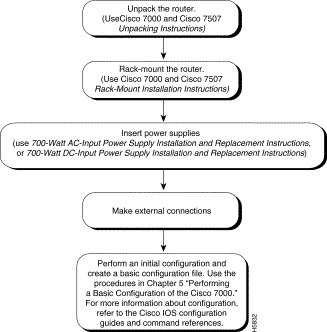
Figure 2-1 shows a flowchart that illustrates the order of procedures required to install the Cisco 7000 router and connect cables. The flowchart also indicates other Cisco publications you should refer to for information.

 | Warning Before working on a chassis or working near power supplies, unplug the power cord on AC units or disconnect the power at the circuit breaker on DC units. (For translated versions of this warning, refer to the appendix "Translated Safety Warnings.") |
 | Warning Do not touch the power supply when the power cord is connected. For systems with a power switch, line voltages are present within the power supply even when the power switch is off and the power cord is connected. For systems without a power switch, line voltages are present within the power supply when the power cord is connected. (For translated versions of this warning, refer to the appendix "Translated Safety Warnings.") |
Electrostatic discharge (ESD) can damage equipment and impair electrical circuitry. It occurs when electronic components are improperly handled and can result in intermittent or complete failures. Always follow ESD-prevention procedures when removing and replacing components. Ensure that the chassis is electrically connected to earth ground. Wear an ESD-preventive wrist strap, ensuring that it makes good skin contact. To safely channel unwanted ESD voltages to ground, connect the clip to an unpainted surface of the chassis frame. If no wrist strap is available, ground yourself to the metal chassis.
 | Caution For safety, periodically check the resistance value of the ESD-preventive wrist strap, which should be between 1 and 10 megohms. |
Depending on your configuration, you might need to insert additional or new processor modules in your Cisco 7000. To insert or remove interface processors, you do not need to turn off power to the system; they support online insertion and removal (OIR). Interface processors include AIP, CIP, EIP, FEIP, FIP, FSIP, HIP, MIP, and TRIP. However, you must turn off the system power before you insert or remove the RP, SP, or SSP, RSP7000, or RSP7000CI processor modules.
You need a number 1 Phillips or 3/16-inch flat-blade screwdriver to remove any fillers (blank processor module carriers) and to tighten the captive installation screws that secure the processor module in its slot. Whenever you handle modules, you should use an ESD-preventive wrist strap or other grounding device to prevent ESD damage.
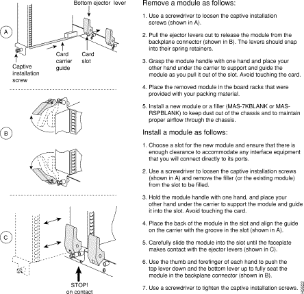
You can install interface processors (as shown in Figure 2-2) in any of the five interface processor slots, numbered 0 through 4 from left to right when viewing the chassis from the rear. (Also refer to the illustration of the Cisco 7000 in Figure 1-1.) The two far-right slots contain the SP (or SSP) and RP, or the optional 7000 RSP and 7000 RSP CI, which are required system components.
 | Caution To prevent the overheating of internal components, always install fillers in empty slots to maintain the proper flow of cooling air across the processor modules. To prevent ESD damage, handle processor modules by the handles and carrier edges only. |
Figure 2-2 illustrates how to remove and replace processor modules.

![]()
![]()
![]()
![]()
![]()
![]()
![]()
![]()
Posted: Fri Oct 19 16:52:56 PDT 2001
All contents are Copyright © 1992--2001 Cisco Systems, Inc. All rights reserved.
Important Notices and Privacy Statement.