|
|

Product Numbers: CX-FSIP4=, CX-FSIP8=, PA-7KF-SPA=, UPG-FSIP4, UPG-FSIP8, UPG-7KF-SPA
This configuration note contains instructions for installing and configuring the Fast Serial Interface Processor (FSIP) in Cisco 7000 series or Cisco 7500 series routers. Included are basic configuration steps and examples.
The following sections are included in this configuration note:
The Cisco IOS software running your router contains extensive features and functionality. The effective use of many interface processor features is easier if you have more information at hand. For additional information on configuring the Cisco 7000 series and Cisco 7500 series routers and interface processors, the following documentation resources are available:
The FSIP (see Figure 1) provides four or eight channel-independent, synchronous serial ports that support full-duplex operation at T1 (1.544 megabits per second [Mbps]) and E1 (2.048 Mbps) speeds. The FSIP ships as Product Numbers CX-FSIP4(=) and CX-FSIP8(=).
The ports are divided into two 4-port modules, each of which is controlled by a dedicated Motorola MC68040 processor and contains 128 kilobytes (KB) of static random-access memory (SRAM). Each module can support up to four T1 or three E1 interfaces, and an aggregate bandwidth of up to 6.132 Mbps at full-duplex operation.
Additional port adapters are available as spares so that you can replace one that fails; however, you cannot upgrade a 4-port FSIP to an 8-port FSIP by adding port adapters. (The 4-port FSIP is not constructed to support additional ports after it leaves the factory; it contains the circuitry to control only one 4-port module.)
An adapter cable provides the network connection for each port and determines the electrical interface type and mode of that interface. (For more information, refer to the section "FSIP Port Adapters, Interface Cables, and Connections" on page 20.)
Each serial port on the FSIP4 or FSIP8 can transmit and receive data at the rate of 6.132 Mbps; however, if one or more ports consumes the full 6.132 Mbps bandwidth, then we strongly recommend that the remaining ports be administratively shut down.
For example, you can configure four T1 interfaces on a module (one T1 on each port) such that they do not exceed 6.132 Mbps, or you can configure one port to operate at up to 6.132 Mbps, and leave the remaining three ports shut down. Note that some environments will support four E1 interfaces per module without any problems; however, the type of electrical interface, the amount of traffic processed, and the types of external data service units (DSUs) connected to the ports affect actual rates.
In addition, all FSIP interface types support nonreturn to zero (NRZ) and nonreturn to zero inverted (NRZI) format, and both 16-bit and 32-bit cyclic redundancy checks (CRCs). The default configuration is for NRZ format and 16-bit CRC. You can change the default settings with software commands. (See the section "Configuring the FSIP" on page 37.)
There is no default mode or clock rate set on the FSIP ports, although an internal clock signal is present on all ports for DCE support. The internal clock also allows you to perform local loopback tests without having to terminate the port or connect a cable. (All interface types except X.21 DTE support loopback.)
To use the port as a DCE interface, you must set the clock rate and connect a DCE adapter cable. To use the port as a DTE interface, you need only connect a DTE adapter cable to the port. Because the serial adapter cables determine the mode and interface type, the FSIP port becomes a DTE when a DTE cable is connected to it.
If a DTE cable is connected to a port with a clock rate set (using the clockrate command), the DTE ignores the clock rate and uses the external clock signal that is sent from the remote DCE. (For a brief description of the clockrate command, refer to the section "Configuring Timing (Clock) Signals" on page 39.)
Each E1-G.703/G.704 interface is a 2.048-megabit per second (Mbps), E1 telecommunications interface; all the other available FSIP interfaces are synchronous serial data communications interfaces. G.703 is an International Telecommunication Union Telecommunication Standardization Sector (ITU-T) electrical and mechanical specification for connections between telecommunications interfaces and data communications equipment (DTE).
Serial signals can travel a limited distance at any given bit rate; generally, the slower the baud rate, the greater the distance. All serial signals are subject to distance limits beyond which a signal degrades significantly or is completely lost. Table 1 lists the recommended maximum speeds and distances for each FSIP serial interface type.
| EIA/TIA-232 Maximum Distances | EIA/TIA-449, X.21, V.35, EIA-530 Maximum Distances | ||||
|---|---|---|---|---|---|
| Rate (bps) | Feet | Meters | Feet | Meters | |
2,400 | 200 | 60 |
| 4,100 | 1,250 |
4,800 | 100 | 30 |
| 2,050 | 625 |
9,600 | 50 | 15 |
| 1,025 | 312 |
19,200 | 25 | 7.6 |
| 513 | 156 |
38,400 | 12 | 3.7 |
| 256 | 78 |
56,000 | 8.6 | 2.6 |
| 102 | 31 |
1,544,000 (T1) | - | - |
| 50 | 15 |
Balanced drivers allow EIA/TIA-449 signals to travel greater distances than EIA/TIA-232. The recommended distance limits for EIA/TIA-449 shown in Table 1 are also valid for V.35, X.21, and EIA-530. However, you can get good results at distances and rates far greater than these. While EIA/TIA-449 and EIA-530 support 2-Mbps rates, and V.35 supports 4-Mbps rates without any problems, we do not recommend exceeding published specifications for transmission speed versus distance; do so at your own risk.
Unbalanced G.703 interfaces allow for a longer maximum cable length than those specified for balanced circuits. Table 2 lists the maximum cable lengths for each FSIP E1-G.703/G.704 cable type by the connector used at the network (non-FSIP) end.
| Connection Type | BNC | Twinax |
|---|---|---|
Balanced | - | 300 m |
Unbalanced | 600 m | - |
Before you install the FSIP, ensure that your existing system components meet the compatibility requirements described in this section. You should also review the safety and ESD-prevention guidelines for avoiding bodily injury or equipment damage, and the list of parts and tools you will need to perform the installation.
The FSIP is compatible with any Cisco 7000 series router that is operating with the following software and microcode:
 | Caution SP Microcode Version 1.4 must reside in ROM; it cannot be loaded from Flash memory. During the boot process, the system accesses the SP (or SSP) microcode. If the SP microcode ROM contains a version earlier than 1.4 and the router contains an FSIP, the system might fail to boot properly. |
Various show commands allow you to display and verify system status and configuration information. The show version command displays the current hardware configuration and the currently loaded and running version of system software. The show controllers cxbus command lists all interfaces and includes the currently loaded and running microcode version for each. You can check the version of the default ROM image either by removing the board and checking the ROM labels or by configuring the system to load the microcode from ROM, restarting the system, and using these same commands to check the running version. For details of these commands, refer to the section "Using Show Commands to Check the Configuration" on page 46.
When the system starts up, it looks for boot instructions in the system configuration file and hardware configuration register. These instructions cause the system to boot from one of three possible sources: the default ROM software, an image stored in Flash memory, or a remote server. Because the system must be able to retrieve and interpret these instructions before it can execute them, it always performs a partial boot from the default ROMs first and, after retrieving the instructions, it executes them and reboots if necessary.
In Cisco 7000 series routers, this partial boot is usually transparent to the user; however, it may generate a harmless error message if the system ROMs contain a software version earlier than Maintenance Release 9.17(5).
In the Cisco 7000 series, Maintenance Release 9.17(5) supports the FSIP, but earlier releases will not recognize it. If the software ROMs in your system contain Maintenance Release 9.17(4) or earlier, the initial, partial boot from that ROM image can cause the following message to be displayed:
%UCODE-3-LDFAIL: Unable to download ucode FSIPn-n in slot 0, installed ucode loaded

must be a SIP serial interface
Booting gs7-k...
This message, which is displayed at each subsequent system startup (unless you remove the FSIP or replace the system software ROMs with Maintenance Release 9.17[5] or later ROMs), does not indicate a problem and should be ignored.
You need the following tools and parts to install or upgrade an FSIP. If you need additional equipment, contact your service representative for ordering information.
This section lists safety guidelines to follow when working with any equipment that connects to electrical power or telephone wiring.
Safety warnings appear throughout this publication in procedures that, if performed incorrectly, might harm you. A warning symbol precedes each warning statement.
Warning 
Means danger. You are in a situation that could cause bodily injury. Before you work on any equipment, be aware of the hazards involved with electrical circuitry and be familiar with standard practices for preventing accidents. To see translations of the warnings that appear in this publication, refer to the Regulatory Compliance and Safety Information document that accompanied this device.
Waarschuwing Dit waarschuwingssymbool betekent gevaar. U verkeert in een situatie die lichamelijk letsel kan veroorzaken. Voordat u aan enige apparatuur gaat werken, dient u zich bewust te zijn van de bij elektrische schakelingen betrokken risico's en dient u op de hoogte te zijn van standaard maatregelen om ongelukken te voorkomen. Voor vertalingen van de waarschuwingen die in deze publicatie verschijnen, kunt u het document Regulatory Compliance and Safety Information (Informatie over naleving van veiligheids- en andere voorschriften) raadplegen dat bij dit toestel is ingesloten.
Varoitus Tämä varoitusmerkki merkitsee vaaraa. Olet tilanteessa, joka voi johtaa ruumiinvammaan. Ennen kuin työskentelet minkään laitteiston parissa, ota selvää sähkökytkentöihin liittyvistä vaaroista ja tavanomaisista onnettomuuksien ehkäisykeinoista. Tässä julkaisussa esiintyvien varoitusten käännökset löydät laitteen mukana olevasta Regulatory Compliance and Safety Information -kirjasesta (määräysten noudattaminen ja tietoa turvallisuudesta).
Attention Ce symbole d'avertissement indique un danger. Vous vous trouvez dans une situation pouvant causer des blessures ou des dommages corporels. Avant de travailler sur un équipement, soyez conscient des dangers posés par les circuits électriques et familiarisez-vous avec les procédures couramment utilisées pour éviter les accidents. Pour prendre connaissance des traductions d'avertissements figurant dans cette publication, consultez le document Regulatory Compliance and Safety Information (Conformité aux règlements et consignes de sécurité) qui accompagne cet appareil.
Warnung Dieses Warnsymbol bedeutet Gefahr. Sie befinden sich in einer Situation, die zu einer Körperverletzung führen könnte. Bevor Sie mit der Arbeit an irgendeinem Gerät beginnen, seien Sie sich der mit elektrischen Stromkreisen verbundenen Gefahren und der Standardpraktiken zur Vermeidung von Unfällen bewußt. Übersetzungen der in dieser Veröffentlichung enthaltenen Warnhinweise finden Sie im Dokument Regulatory Compliance and Safety Information (Informationen zu behördlichen Vorschriften und Sicherheit), das zusammen mit diesem Gerät geliefert wurde.
Avvertenza Questo simbolo di avvertenza indica un pericolo. La situazione potrebbe causare infortuni alle persone. Prima di lavorare su qualsiasi apparecchiatura, occorre conoscere i pericoli relativi ai circuiti elettrici ed essere al corrente delle pratiche standard per la prevenzione di incidenti. La traduzione delle avvertenze riportate in questa pubblicazione si trova nel documento Regulatory Compliance and Safety Information (Conformità alle norme e informazioni sulla sicurezza) che accompagna questo dispositivo.
Advarsel Dette varselsymbolet betyr fare. Du befinner deg i en situasjon som kan føre til personskade. Før du utfører arbeid på utstyr, må du vare oppmerksom på de faremomentene som elektriske kretser innebærer, samt gjøre deg kjent med vanlig praksis når det gjelder å unngå ulykker. Hvis du vil se oversettelser av de advarslene som finnes i denne publikasjonen, kan du se i dokumentet Regulatory Compliance and Safety Information (Overholdelse av forskrifter og sikkerhetsinformasjon) som ble levert med denne enheten.
Aviso Este símbolo de aviso indica perigo. Encontra-se numa situação que lhe poderá causar danos físicos. Antes de começar a trabalhar com qualquer equipamento, familiarize-se com os perigos relacionados com circuitos eléctricos, e com quaisquer práticas comuns que possam prevenir possíveis acidentes. Para ver as traduções dos avisos que constam desta publicação, consulte o documento Regulatory Compliance and Safety Information (Informação de Segurança e Disposições Reguladoras) que acompanha este dispositivo.
¡Advertencia! Este símbolo de aviso significa peligro. Existe riesgo para su integridad física. Antes de manipular cualquier equipo, considerar los riesgos que entraña la corriente eléctrica y familiarizarse con los procedimientos estándar de prevención de accidentes. Para ver una traducción de las advertencias que aparecen en esta publicación, consultar el documento titulado Regulatory Compliance and Safety Information (Información sobre seguridad y conformidad con las disposiciones reglamentarias) que se acompaña con este dispositivo.
Varning! Denna varningssymbol signalerar fara. Du befinner dig i en situation som kan leda till personskada. Innan du utför arbete på någon utrustning måste du vara medveten om farorna med elkretsar och känna till vanligt förfarande för att förebygga skador. Se förklaringar av de varningar som förkommer i denna publikation i dokumentet Regulatory Compliance and Safety Information (Efterrättelse av föreskrifter och säkerhetsinformation), vilket medföljer denna anordning.
Follow these basic guidelines when working with any electrical equipment:
Use the following guidelines when working with any equipment that is connected to telephone wiring or to other network cabling:
Following are guidelines for preventing ESD damage:
| Caution For safety, periodically check the resistance value of the antistatic strap. The measurement should be between 1 and 10 megohms. |
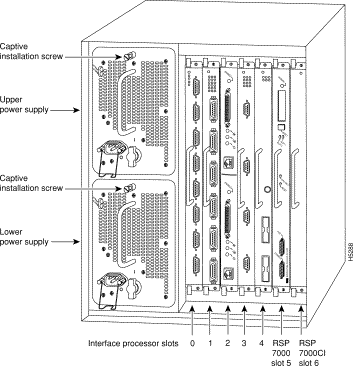
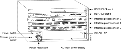
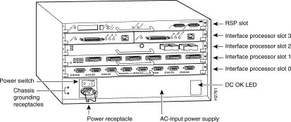
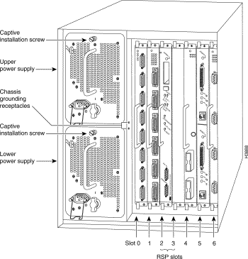
The FSIP is installed in the interface processor slots in the Cisco 7000 series and Cisco 7500 series routers. The interface processor slots in the Cisco 7000 series and Cisco 7500 series routers are as follows:
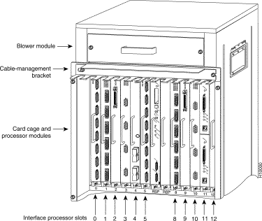
This section describes the mechanical functions of system components and emphasizes the importance of following correct procedures to avoid unnecessary board failures. Specific procedures follow these general background and safety guidelines in the section "Interface Processor Replacement Procedures" on page 15.
You can remove and replace interface processors while the system is operating; you do not need to notify the software or reset the system power. This functionality enables you to add, remove, or replace interface processors with the system online, which provides a method that is seamless to end users on the network, maintains all routing information, and ensures session preservation.
After an interface processor is reinstalled, the system brings on line only interfaces that match the current configuration and were previously configured as up; all others require that you configure them with the configure command.
| Caution The system can indicate a hardware failure if you do not follow proper procedures. Remove or insert only one interface processor at a time. Allow at least 15 seconds for the system to complete the preceding tasks before removing or inserting another interface processor. Disrupting the sequence before the system completes its verification can cause the system to interpret hardware failures. |
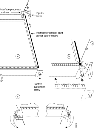
All interface processors have ejector levers that allow you to firmly seat an interface processor in the interface processor slot (see Figure 8). The function of the ejector levers is to align and seat the card connectors in the backplane. Failure to use the ejector levers and insert the interface processor properly can disrupt the order in which the pins make contact with the backplane.
It is also important to use the ejector levers when removing an interface processor to ensure that the board connector pins disconnect from the backplane in the logical sequence expected by the system. Any processor module (interface processor or RSP) that is only partially connected to the backplane can hang the bus. (Detailed steps for correctly installing and removing an interface processor follow in the section "Interface Processor Replacement Procedures.")
The following sections describe the procedures for removing or installing an interface processor. (Refer the section "Guidelines for Interface Processor Removal and Installation" before removing an interface processor while power to the system is on.)
| Caution To avoid erroneous failure messages, remove or insert only one interface processor at a time. Also, after inserting or removing an interface processor, allow at least 15 seconds before removing or inserting another interface processor so that the system can reinitialize and note the current configuration of all interfaces. |
If you have a Cisco 7507 or a Cisco 7513 with an RSP2 configured as the system slave, we strongly recommend that you use the following procedure to remove and replace an interface processor:
Step 1 Remove the slave RSP2.
Step 2 Wait 15 seconds.
Step 3 Remove and replace the interface processor using the procedures in this publication.
Step 4 Wait 15 seconds.
Step 5 Reinsert the slave RSP2.
Figure 7 shows proper handling of an interface processor during installation. Before you remove an interface processor that you will not replace, or replace an interface processor component, we recommend you shut down (disable) the interfaces to prevent anomalies when you reinstall the new or reconfigured interface processor. When you shut down an interface, it is designated administratively down in the show command displays.
Use the following procedure to remove an interface processor:
Step 1 Disconnect the interface processor's cables from the interface ports.
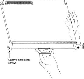
Step 2 Loosen the captive installation screws at the ends of the interface processor faceplate. (See Figure 8a.)
| Caution Always use the ejector levers to remove or install an interface processor. Failure to do so can cause erroneous system error messages, indicating a board failure. |
Step 3 Place your thumbs on the upper and lower ejector levers and simultaneously push the top ejector lever up and the bottom ejector lever down (in the opposite direction from that shown in Figure 8c) to release an interface processor from the backplane connector.
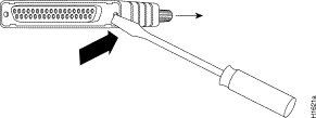
Step 4 Grasp the interface processor handle with one hand and place your other hand under the carrier to guide the interface processor out of the slot. (See Figure 7.) Avoid touching the board or any connector pins.
Step 5 Carefully pull the interface processor straight out of the slot, keeping one hand under the carrier to guide it. (See Figure 7.) Keep the interface processor parallel to the backplane.
Step 6 Place the removed interface processor on an antistatic mat or foam pad, or place it in an antistatic bag if you will return it to the factory.
If you install a new interface processor, you have to first remove the interface processor filler from the available interface processor slot. Figure 8 shows functional details of inserting an interface processor and using ejector levers. (Figure 7 shows proper handling of an interface processor during installation.)
| Caution Remove or insert only one interface processor at a time. Allow at least 15 seconds for the system to complete the preceding tasks before removing or inserting another interface processor. Disrupting the sequence before the system completes its verification can cause the system to interpret this as a hardware failure. |
Use the following procedure to install an interface processor:
Step 1 Ensure that a console terminal is connected to the RP (or RSP) Console port and that the console is turned on.
Step 2 Choose an available interface processor slot for the interface processor, and ensure that the interface processor's cable is of a sufficient length to connect the interface processor with any external equipment. We recommend that you install interface processors starting with the slots closest to the RSPs and work out concentrically from there. This will help prevent EMI.
Step 3 Interface processors and interface processor fillers are secured with two captive installation screws. (See Figure 8a.) Use a flat-blade screwdriver to loosen the captive installation screws and remove the interface processor filler (or the existing interface processor) from the slot. If you remove an interface processor, immediately place it in an antistatic bag to prevent damage from electrostatic discharge.
Step 4 Hold the interface processor handle with one hand, and place your other hand under the carrier to support the interface processor (see Figure 7); guide the carrier into the slot. Avoid touching the card or any connector pins.
| Caution To prevent ESD damage, handle interface processors by the handles and carrier edges only. |
Step 5 Place the back of the interface processor in the slot and align the notch on the bottom of the carrier with the groove in the slot. (See Figure 8a.)
Step 6 While keeping the interface processor parallel to the backplane, carefully slide the interface processor into the slot until the back of the faceplate makes contact with the ejector levers, then stop. (See Figure 8b.)
| Caution Always use the ejector levers when installing or removing processor modules. A module that is partially seated in the backplane will cause the system to hang and subsequently crash. |
Step 7 Using the thumb and forefinger of each hand to pinch each ejector lever, simultaneously push the top ejector lever down and the bottom ejector lever up until both are parallel to the faceplate. (See Figure 8c.)
Step 8 Tighten the captive screws on the top and bottom of the interface processor faceplate to prevent the interface processor from becoming partially dislodged from the backplane and ensure proper EMI shielding. (These screws must be tightened to meet EMI specifications.)
| Caution To ensure adequate space for additional interface processors, always tighten the captive installation screws on each newly installed interface processor before you insert any additional interface processors. These screws also prevent accidental removal, and provide proper grounding and EMI shielding for the system. |
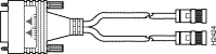
The universal port adapters and adapter cables allow eight interface ports on an FSIP, regardless of the size of the connectors typically used with each electrical interface type. (See Figure 9.)
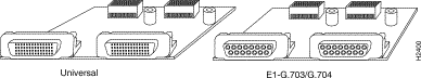
Port adapters are field-replaceable daughter boards mounted to the FSIP, and each provides two high-density connectors for two FSIP ports.
All FSIP port adapters use an identical 60-pin, D-shell receptacle that supports all interface types: EIA/TIA-232, V.35, EIA/TIA-449, X.21, and EIA-530. An exception to this is the E1-G.703/G.704 port adapter, which uses a 15-pin, D-shell receptacle.
Each port requires a serial interface adapter cable that provides the interface between the high-density FSIP port and the standard connectors that are commonly used for each electrical interface type. Rate of data transmission depends on the type of electrical interface: EIA/TIA-232 for speeds of 64 kilobits per second (kbps) and below; X.21, EIA/TIA-449, V.35, or EIA-530 for higher speeds.
The router (FSIP) end of all adapter cables is a 60-pin, D-shell plug that connects to the 60-pin port on the FSIP. The network end of the cable is an industry-standard connector for the type of electrical interface that the cable supports. For most interface types, the adapter cable for DTE mode uses a plug at the network end, and the cable for DCE mode uses a receptacle at the network end. Exceptions are V.35 adapter cables, which are available with either a V.35 plug or a receptacle for either mode, and the EIA-530 adapter cable, which is available only in DTE mode with a DB-25 plug at the network end.
Following are the available port adapter and cable options for the mode and network-end connectors for each synchronous serial cable listed by product number:
Following are the available port adapter and cable options for the E1-G.703/G.704 interface:
All cables and port adapters are available as spare parts (=).
For replacement instructions, refer to the configuration note that shipped with your replacement port adapter. For cable pinouts, refer to the section "FSIP Port Adapter Interface and Cable Pinouts" on page 23.
Figure 10 shows the synchronous serial port adapter cables for connecting the FSIP port adapters to your network.
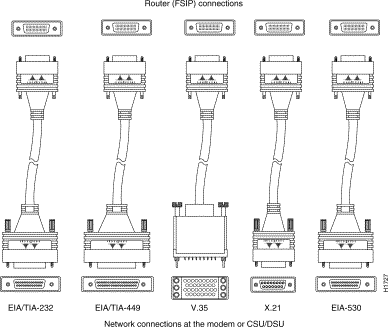
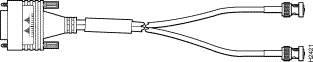
Figure 11, Figure 12, and Figure 13 show the unbalanced and balanced cables used for connecting the E1-G.703/G.704 port adapter and your network. The port-adapter end of each cable has a DB-15 connector.
| Caution It is a requirement of the statutory approval of the E1-G.703/G.704 interface that the jackscrews of the connector backshell be securely screwed down while the FSIP is operating. |
Metric (M3) thumbscrews are included with each port adapter cable to allow connections to devices that use metric hardware. Because the FSIP uses a special, high-density port that requires special adapter cables for each electrical interface type, we recommend that you obtain serial interface cables from the factory.
The FSIP supports EIA/TIA-232, EIA/TIA-449, X.21, V.35, and EIA-530 serial interfaces and the E1-G.703/G.704 interface. All FSIP ports use a universal port adapter, which is a 60-pin receptacle that supports all available interface types. A special synchronous serial adapter cable, which is required for each synchronous port, determines the electrical interface type and mode of the synchronous serial interface. The router (FSIP) end of all of the adapter cables is a 60-pin plug; the connectors at the network end are the standard connectors used for the respective interfaces. An exception to this is the E1-G.703/G.704 port adapter, which uses a 15-pin, D-shell receptacle.
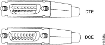
All synchronous serial interface types except EIA-530 are available in DTE or DCE format: DTE with a plug connector at the network end and DCE with a receptacle at the network end. V.35 is available in either mode with either gender at the network end. EIA-530 is available in DTE only.
The tables that follow list the signal pinouts for both the DTE and DCE mode serial port adapter cables for each FSIP interface type:
| DTE Cable | DCE Cable | ||||||||||
|---|---|---|---|---|---|---|---|---|---|---|---|
| FSIP End, HD1 60-Position Plug | Network End, DB-25 Plug | FSIP End, HD 60-Position Plug | Network End, DB-25 Receptacle | ||||||||
| Signal | Pin | Pin | Signal | Signal | Pin | Pin | Signal | ||||
Shield ground | 46 |
| 1 | Shield ground |
|
| Shield ground | 46 |
| 1 | Shield ground |
TxD/RxD | 41 | —> | 2 | TxD |
|
| RxD/TxD | 36 | <— | 2 | TxD |
RxD/TxD | 36 | <— | 3 | RxD |
|
| TxD/RxD | 41 | —> | 3 | RxD |
RTS/CTS | 42 | —> | 4 | RTS |
|
| CTS/RTS | 35 | <— | 4 | RTS |
CTS/RTS | 35 | <— | 5 | CTS |
|
| RTS/CTS | 42 | —> | 5 | CTS |
DSR/DTR | 34 | <— | 6 | DSR |
|
| DTR/DSR | 43 | —> | 6 | DSR |
Circuit ground | 45 |
| 7 | Circuit ground |
|
| Circuit ground | 45 |
| 7 | Circuit ground |
DCD/LL | 33 | <— | 8 | DCD |
|
| LL/DCD | 44 | —> | 8 | DCD |
TxC/NIL | 37 | <— | 15 | TxC |
|
| TxCE/TxC | 39 | —> | 15 | TxC |
RxC/TxCE | 38 | <— | 17 | RxC |
|
| NIL/RxC | 40 | —> | 17 | RxC |
LL/DCD | 44 | —> | 18 | LTST |
|
| DCD/LL | 33 | <— | 18 | LTST |
DTR/DSR | 43 | —> | 20 | DTR |
|
| DSR/DTR | 34 | <— | 20 | DTR |
TxCE/TxC | 39 | —> | 24 | TxCE |
|
| RxC/TxCE | 38 | <— | 24 | TxCE |
Mode 0 | 50 |
|
| |
|
| Mode 0 | 50 |
|
| |
| 1HD = high density. |
| DTE Cable | DCE Cable | ||||||||||
|---|---|---|---|---|---|---|---|---|---|---|---|
| FSIP End, HD1 60-Position Plug | Network End, DB-37 Plug | FSIP End, HD 60-Position Plug | Network End, DB-37 Receptacle | ||||||||
| Signal | Pin | Pin | Signal | Signal | Pin | Pin | Signal | ||||
Shield ground | 46 | 1 | Shield ground |
|
| Shield ground | 46 |
| 1 | Shield ground | |
TxD/RxD+ | 11 | —> | 4 | SD+ |
|
| RxD/TxD+ | 28 | <— | 4 | SD+ |
TxD/RxD- | 12 | —> | 22 | SD- |
|
| RxD/TxD- | 27 | <— | 22 | SD- |
TxC/RxC+ | 24 | <— | 5 | ST+ |
|
| TxCE/TxC+ | 13 | —> | 5 | ST+ |
TxC/RxC- | 23 | <— | 23 | ST- |
|
| TxCE/TxC- | 14 | —> | 23 | ST- |
RxD/TxD+ | 28 | <— | 6 | RD+ |
|
| TxD/RxD+ | 11 | —> | 6 | RD+ |
RxD/TxD- | 27 | <— | 24 | RD- |
|
| TxD/RxD- | 12 | —> | 24 | RD- |
RTS/CTS+ | 9 | —> | 7 | RS+ |
|
| CTS/RTS+ | 1 | <— | 7 | RS+ |
RTS/CTS- | 10 | —> | 25 | RS- |
|
| CTS/RTS- | 2 | <— | 25 | RS- |
RxC/TxCE+ | 26 | <— | 8 | RT+ |
|
| TxC/RxC+ | 24 | —> | 8 | RT+ |
RxC/TxCE- | 25 | <— | 26 | RT- |
|
| TxC/RxC- | 23 | —> | 26 | RT- |
CTS/RTS+ | 1 | <— | 9 | CS+ |
|
| RTS/CTS+ | 9 | —> | 9 | CS+ |
CTS/RTS- | 2 | <— | 27 | CS- |
|
| RTS/CTS- | 10 | —> | 27 | CS- |
LL/DCD | 44 | —> | 10 | LL |
|
| NIL/LL | 29 | —> | 10 | LL |
Circuit ground | 45 |
| 37 | SC |
|
| Circuit ground | 30 |
| 37 | SC |
DSR/DTR+ | 3 | <— | 11 | ON+ |
|
| DTR/DSR+ | 7 | —> | 11 | ON+ |
DSR/DTR- | 4 | <— | 29 | ON- |
|
| DTR/DSR- | 8 | —> | 29 | ON- |
DTR/DSR+ | 7 | —> | 12 | TR+ |
|
| DSR/DTR+ | 3 | <— | 12 | TR+ |
DTR/DSR- | 8 | —> | 30 | TR- |
|
| DSR/DTR- | 4 | <— | 30 | TR- |
DCD/DCD+ | 5 | <— | 13 | RR+ |
|
| DCD/DCD+ | 5 | —> | 13 | RR+ |
DCD/DCD- | 6 | <— | 31 | RR- |
|
| DCD/DCD- | 6 | —> | 31 | RR- |
TxCE/TxC+ | 13 | —> | 17 | TT+ |
|
| RxC/TxCE+ | 26 | <— | 17 | TT+ |
TxCE/TxC- | 14 | —> | 35 | TT- |
|
| RxC/TxCE- | 25 | <— | 35 | TT- |
Circuit ground | 15 |
| 19 | SG |
|
| Circuit ground | 15 |
| 19 | SG |
Circuit ground | 16 |
| 20 | RC |
|
| Circuit ground | 16 |
| 20 | RC |
Mode 1 | 49 |
|
| Shorting group |
|
| Mode 1 | 49 |
|
| Shorting group |
Ground | 51 |
|
| Shorting group |
|
|
|
|
|
|
|
| 1HD = high density. |
| DTE Cable | DCE Cable | |||||||||
|---|---|---|---|---|---|---|---|---|---|---|
| FSIP End, HD1 60-Position Plug | Network End, DB-15 Plug | FSIP End, HD 60-Position Plug | Network End, DB-15 Receptacle | |||||||
| Signal | Pin | Pin | Signal | Signal | Pin | Pin | Signal | |||
Shield ground | 46 |
| 1 | Shield ground |
| Shield ground | 46 |
| 1 | Shield ground |
TxD/RxD+ | 11 | —> | 2 | Transmit+ |
| RxD/TxD+ | 28 | <— | 2 | Transmit+ |
TxD/RxD- | 12 | —> | 9 | Transmit- |
| RxD/TxD- | 27 | <— | 9 | Transmit- |
RTS/CTS+ | 9 | —> | 3 | Control+ |
| CTS/RTS+ | 1 | <— | 3 | Control+ |
RTS/CTS - | 10 | —> | 10 | Control- |
| CTS/RTS - | 2 | <— | 10 | Control- |
RxD/TxD+ | 28 | <— | 4 | Receive+ |
| TxD/RxD+ | 11 | —> | 4 | Receive+ |
RxD/TxD- | 27 | <— | 11 | Receive- |
| TxD/RxD- | 12 | —> | 11 | Receive- |
CTS/RTS+ | 1 | <— | 5 | Indication+ |
| RTS/CTS+ | 9 | —> | 5 | Indication+ |
CTS/RTS - | 2 | <— | 12 | Indication- |
| RTS/CTS- | 10 | —> | 12 | Indication- |
RxC/TxCE+ | 26 | <— | 6 | Timing+ |
| TxC/RxC+ | 24 | —> | 6 | Timing+ |
RxC/TxCE- | 25 | <— | 13 | Timing- |
| TxC/RxC - | 23 | —> | 13 | Timing- |
Circuit ground | 15 |
| 8 | Circuit ground |
| Circuit ground | 15 |
| 8 | Circuit ground |
Ground | 48 |
|
| Shorting group |
| Ground | 48 |
|
| Shorting |
Ground | 51 |
|
| Shorting group |
| Ground | 51 |
|
|
|
| 1HD = high density. |
| DTE Cable | DCE Cable | |||||||||
|---|---|---|---|---|---|---|---|---|---|---|
| FSIP End, HD1 60-Position Plug | Network End, 34-Position Plug | FSIP End, HD 60-Position Plug | Network End, 34-Position Receptacle | |||||||
| Signal | Pin |
| Pin | Signal | Signal | Pin |
| Pin | Signal | |
Shield ground | 46 |
| A | Frame ground |
| Shield ground | 46 |
| A | Frame ground |
Circuit ground | 45 |
| B | Circuit ground |
| Circuit ground | 45 |
| B | Circuit ground |
RTS/CTS | 42 | —> | C | RTS |
| CTS/RTS | 35 | <— | C | RTS |
CTS/RTS | 35 | <— | D | CTS |
| RTS/CTS | 42 | —> | D | CTS |
DSR/DTR | 34 | <— | E | DSR |
| DTR/DSR | 43 | —> | E | DSR |
DCD/LL | 33 | <— | F | RLSD |
| LL/DCD | 44 | —> | F | RLSD |
DTR/DSR | 43 | —> | H | DTR |
| DSR/DTR | 34 | <— | H | DTR |
LL/DCD | 44 | —> | K | LT |
| DCD/LL | 33 | <— | K | LT |
TxD/RxD+ | 18 | —> | P | SD+ |
| RxD/TxD+ | 28 | <— | P | SD+ |
TxD/RxD- | 17 | —> | S | SD- |
| RxD/TxD- | 27 | <— | S | SD- |
RxD/TxD+ | 28 | <— | R | RD+ |
| TxD/RxD+ | 18 | —> | R | RD+ |
RxD/TxD- | 27 | <— | T | RD- |
| TxD/RxD- | 17 | —> | T | RD- |
TxCE/TxC+ | 20 | —> | U | SCTE+ |
| RxC/TxCE+ | 26 | <— | U | SCTE+ |
TxCE/TxC- | 19 | —> | W | SCTE- |
| RxC/TxCE- | 25 | <— | W | SCTE- |
RxC/TxCE+ | 26 | <— | V | SCR+ |
| NIL/RxC+ | 22 | —> | V | SCR+ |
RxC/TxCE- | 25 | <— | X | SCR- |
| NIL/RxC- | 21 | —> | X | SCR- |
TxC/RxC+ | 24 | <— | Y | SCT+ |
| TxCE/TxC+ | 20 | —> | Y | SCT+ |
TxC/RxC- | 23 | <— | AA | SCT- |
| TxCE/TxC- | 19 | —> | AA | SCT- |
Mode 1 | 49 |
|
| Shorting group |
| Mode 1 | 49 |
|
| Shorting group |
Mode 0 | 50 |
|
| Shorting group |
| Mode 0 | 50 |
|
| Shorting group |
TxC/NIL | 53 |
|
| Shorting group |
| TxC/NIL | 53 |
|
| Shorting group |
| 1HD = high density. |
| FSIP End, HD1 60-Position Plug | Network End, DB-25 Plug | |||
|---|---|---|---|---|
| Signal | Pin |
| Pin | Signal |
Shield ground | 46 |
| 1 | Shield ground |
TxD/RxD+ | 11 | —> | 2 | TxD+ |
TxD/RxD- | 12 | —> | 14 | TxD- |
RxD/TxD+ | 28 | <— | 3 | RxD+ |
RxD/TxD- | 27 | <— | 16 | RxC- |
RTS/CTS+ | 9 | —> | 4 | RTS+ |
RTS/CTS- | 10 | —> | 19 | RTS- |
CTS/RTS+ | 1 | <— | 5 | CTS+ |
CTS/RTS- | 2 | <— | 13 | CTS- |
DSR/DTR+ | 3 | <— | 6 | DSR+ |
DSR/DTR- | 4 | <— | 22 | DSR- |
DCD/DCD+ | 5 | <— | 8 | DCD+ |
DCD/DCD- | 6 | <— | 10 | DCD- |
TxC/RxC+ | 24 | <— | 15 | TxC+ |
TxC/RxC- | 23 | <— | 12 | TxC- |
RxC/TxCE+ | 26 | <— | 17 | RxC+ |
RxC/TxCE- | 25 | <— | 9 | RxC- |
LL/DCD | 44 | —> | 18 | LL |
Circuit ground | 45 |
| 7 | Circuit ground |
DTR/DSR+ | 7 | —> | 20 | DTR+ |
DTR/DSR- | 8 | —> | 23 | DTR- |
TxCE/TxC+ | 13 | —> | 24 | TxCE+ |
TxCE/TxC- | 14 | —> | 11 | TxCE- |
Mode_1 | 49 |
|
| |
Ground | 51 |
|
| Shorting group |
| 1HD = high density. |
| FSIP End | Network End | |||||
|---|---|---|---|---|---|---|
| DB-151 | DB-15 | Null Modem DB-15 | BNC | Twinax | ||
| Pin | Signal2 | Pin | Pin | Signal | Pin | Signal |
9 | Tx tip | 1 | 3 | Tx tip | Tip | Tx tip |
2 | Tx ring | 9 | 11 | Tx shield | Ring | Tx ring |
10 | Tx shield | 2 | 4 | - | Shield | Tx shield |
8 | Rx tip | 3 | 1 | Rx tip | Tip | Rx tip |
15 | Rx ring | 11 | 9 | Rx shield | Ring | Rx ring |
7 | Rx shield | 4 | 2 | - | Shield | Rx shield |
| 1Any pins not described in Table 8 are not connected. 2Tx = transmit. Rx = receive. |
Use the information in the following sections for your serial connections:
EIA/TIA-232 supports unbalanced circuits at signal speeds up to 64 kbps. The router (FSIP) end of all EIA/TIA-232 adapter cables is a high-density 60-pin plug. The opposite (network) end of the adapter cable is a standard 25-pin D-shell connector (known as a DB-25) that is commonly used for EIA/TIA-232 connections. Figure 14 shows the connectors at the network end of the adapter cable.
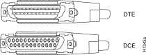
EIA/TIA-449, which supports balanced (EIA/TIA-422) and unbalanced (EIA/TIA-423) transmissions, is a faster (up to 2 Mbps) version of EIA/TIA-232, which provides more functions and supports transmissions over greater distances. The EIA/TIA-449 standard was intended to replace EIA/TIA-232, but it was not widely adopted. The resistance to convert to EIA/TIA-449 was due primarily to the large installed base of DB-25 hardware and to the larger size of the 37-pin EIA/TIA-449 connectors, which limited the number of connections possible (fewer than is possible with the smaller, 25-pin EIA/TIA-232 connector).
The router (FSIP) end of all EIA/TIA-449 adapter cables is a high-density 60-pin plug. The opposite (network) end of the adapter cable provides a standard 37-pin D-shell connector, which is commonly used for EIA/TIA-449 connections.
Figure 15 shows the connectors at the network end of the adapter cable.
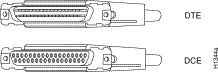
Figure 16 shows the connectors at the network end of the V.35 adapter cable.
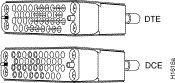
Figure 17 shows the connectors at the network end of the X.21 adapter cable.
The EIA-530 interface, which supports balanced transmission, provides the increased functionality, speed, and distance of EIA/TIA-449 on the smaller, DB-25 connector used for EIA/TIA-232. The EIA-530 interface is used primarily in the United States. The EIA-530 standard was created to support the more sophisticated circuitry of EIA/TIA-449 on the large number of existing EIA/TIA-232 (DB-25) hardware. Like EIA/TIA-449, EIA-530 refers to the electrical specifications of EIA/TIA-422 and EIA/TIA-423. Although the specification recommends a maximum speed of 2 Mbps, EIA-530 is used successfully at 4 Mbps and at even faster speeds over short distances.
Figure 18 shows the DB-25 connector at the network end of the adapter cable.
A pair of metric thumbscrews is included with each port adapter cable except V.35. If you plan to connect serial cables to a remote device that uses metric hardware, replace the standard 4-40 thumbscrews at the network end of the cable with the metric, M3 thumbscrews.
To remove thumbscrews, use the flat side of a large (1/4-inch) flat-blade screwdriver to push the tip of the screw into the connector housing and out the other side. (See Figure 19.) If the screw resists, use pliers to pull it out. Insert the new thumbscrew and push it into the connector housing until it pops into place.
The router (port adapter) end of the FSIP serial interface cables must be connected to the 60-pin receptacles on the port adapter as shown at the top of Figure 20. Although the 60-pin plug on each cable is keyed for proper insertion, it can be forced onto the port adapter's receptacle if you are not careful. Also, older serial cables, with fewer pins, cannot be used for the 60-pin receptacle on the port adapter.
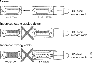
All FSIP ports support any available synchronous serial interface type and mode. The serial adapter cable determines the electrical interface type and mode of the port to which it is connected. E1-G.703/G.704, EIA/TIA-232, EIA/TIA-449, V.35, and X.21 interfaces are available in DTE mode with a plug at the network end and in DCE mode with a receptacle at the network end. EIA-530 is available only in DTE mode with a plug. Connect the FSIP serial cables as shown in Figure 21; however, observe the connection precautions indicated in the section "Cable Connection Precautions" on page 32.
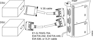
When you connect serial devices, consider the adapter cables as an extension of the router for external connections. Therefore, use DTE cables to connect the router to remote DCE devices such as modems or DSUs, and use DCE cables to connect the router to remote DTE devices such as a host server, PC, or another router.
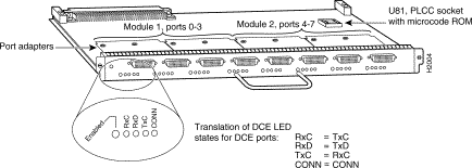
The FSIP has several status LEDs on its faceplate, next to each port, which indicate conditions on that port. (See Figure 22.)
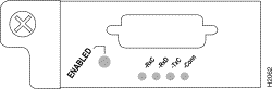
After system initialization, the enabled LED goes on to indicate that the FSIP has been enabled for operation.
The following conditions must be met before the FSIP is enabled:
If any one of these conditions is not met, or if the initialization fails, the enabled LED does not go on.
The four LEDs adjacent to each port indicate the state of that interface. The labels on each LED indicate the signal state when the FSIP port is in DTE mode. When the FSIP port is in DCE mode, the direction of the signals is reversed.
For example, a DCE device usually generates a clock signal, which it sends to the DTE device. Therefore, when the FSIP port is a DTE port, the Receive Clock (RxC) LED indicates that the DTE is receiving the clock signal from the remote DCE device. However, when the FSIP is operating as a DCE, the RxC LED indicates that the DCE is sending a clock signal to the remote DTE device. Only DTE mode states are labeled on each port because of limited space on the FSIP faceplate.
Figure 23 shows the signal flow between DTE and DCE devices and the LEDs that correspond to signals for each mode.
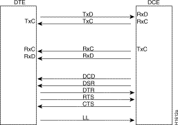
Table 9 lists the LED states for ports in DTE and DCE mode; a more complete explanation follows.
| LED | DTE Signal | DCE Signal |
|---|---|---|
RxC | Receive clock (from DCE) | (TxC) Transmit clock (to DTE) |
RxD | Receive data (from DCE) | (TxD) Transmit data (from DTE) |
TxC | Send timing (from DCE) | (RxC) Receive timing (to DTE) |
Conn | Connected | Connected |
The following LED state descriptions include meanings for both DTE and DCE interfaces:
Verify that the FSIP is connected correctly as follows:
Step 1 While the system reinitializes each interface, observe the console display messages and verify that the system discovers the FSIP. The system should recognize the FSIP interfaces but leave them configured as down.
Step 2 When the reinitialization is complete, verify that the enabled LED on the FSIP is on and remains on. If the LED does stay on, proceed to Step 5. If the enabled LED does not stay on, proceed to the next step.
Step 3 If the enabled LED on the FSIP fails to go on, suspect that the FSIP board connector is not fully seated in the backplane. Loosen the captive installation screws, then firmly push the ejector levers until both are parallel to the FSIP faceplate. Tighten the captive installation screws. After the system reinitializes the interfaces, the enabled LED on the FSIP should go on. If the enabled LED goes on, proceed to Step 5. If the enabled LED does not go on, proceed to the next step.
Step 4 If the enabled LED still fails to go on, remove the FSIP and try installing it in another available interface processor slot.
Step 5 Use the show interfaces or show controllers cbus command to verify the status of the FSIP interfaces. (If the FSIP interfaces are not configured, configure them using the procedures in the section "Configuring the FSIP.")
If you want to change the configuration of an existing interface, you must enter configuration mode to configure the interface. If you replaced an FSIP that was previously configured, the system will recognize the new FSIP interfaces and bring each of them up in their existing configuration.
After you verify that the new FSIP is installed correctly (the enabled LED goes on), use the privileged-level configure command to configure the new interfaces. Be prepared with the information you will need, such as the following:
For complete descriptions of configuration subcommands and the configuration options available for serial interfaces, refer to the appropriate software documentation listed in the section "If You Need More Information" on page 2.
Configuring the FSIP first requires privileged-level access to the EXEC command interpreter. Also, privileged-level access usually requires a password. (Contact your system administrator, if necessary, to obtain privileged-level access.)
Cisco 7000 series and Cisco 7500 series routers identify an interface address by its interface processor slot number and port number in the format slot/port. Each FSIP contains either four or eight serial interfaces. Ports are numbered sequentially beginning with interface 0. For example, the slot/port address of the first interface on an FSIP installed in interface processor slot 0 is 0/0, and the adjacent port on the same FSIP is 0/1.
The following instructions are provided for performing a basic configuration: enabling an interface, specifying IP routing, and setting up external timing on a DCE interface. You might also need to enter other configuration subcommands, depending on the requirements for your system configuration and the protocols you plan to route on the interface.
In the following procedure, press the Return key after each step unless otherwise noted.
Step 1 At the privileged-level prompt, enter configuration mode and specify that the console terminal will be the source of the configuration subcommands, as follows:
Router# configure terminal

Enter configuration commands, one per line. End with CNTL/Z.
Router(config)#
Step 2 At the prompt, specify the first interface to configure by entering the subcommand interface, followed by the type (serial) and slot/port (interface processor slot number/0). The example that follows is for the first port on an FSIP in interface processor slot 0:
Router(config)# interface serial 0/0
Step 3 If IP routing is enabled on the system, you can assign an IP address and subnet mask to the interface with the ip address configuration subcommand, as in the following example:
Router(config-if)# ip address 1.1.1.67 255.255.255.0
Step 4 Add any additional configuration subcommands required to enable routing protocols and adjust the interface characteristics.
Step 5 If you are configuring a DTE interface, proceed to step 7. If you are configuring a DCE interface, you also need to configure the external clock signal, as described in the next step.
Step 6 Set the clock rate with the clockrate command. (For a description of the clockrate command, refer to the section "Configuring Timing (Clock) Signals" which follows.)
Router(config-if)# clockrate 72000
Step 7 Change the shutdown state to up and enable the interface as follows:
Router(config-if)# no shutdown
Step 8 When you have included all of the configuration subcommands to complete the configuration, press Ctrl-Z to exit configuration mode.
Step 9 Write the new configuration to memory as follows:
Router# copy running-config startup-config

[OK]
Router#
Step 10 Exit the privileged level and return to the user level by entering disable at the prompt as follows:
Router# disable

Router>
Proceed to the following section to configure timing signals on your serial interfaces.
To use a port in DCE mode, you must connect a DCE interface cable and set the clock speed with the clockrate configuration command. You must also set the clock rate to perform a loopback test.
This section describes how to set the clock rate on a DCE port and, if necessary, how to invert the clock to correct a phase shift between the data and clock signals.
In the following example, the clock rate for the first serial interface on an FSIP in interface processor slot 0 (0/0) is defined as 72 kbps:
Router(config)# interface serial 0/0

Router(config-if)# clockrate 72000
Use the no clockrate command to remove the clock rate.
Following are the acceptable clockrate settings:
1200, 2400, 4800, 9600, 19200
38400 , 56000 , 64000 , 72000 , 125000
148000 , 500000, 800000, 1000000, 1300000
2000000 , 4000000 , 8000000
Speeds above 64 kbps (64000) are not appropriate for EIA/TIA-232. On all interface types, faster speeds might not work if your cable is too long.
When a port is operating in DCE mode, the default operation is for the attached DTE device to return the Synchronous Clock Transmit Enable (SCTE) signal to the DCE (FSIP port). The DCE sends the Synchronous Clock Transmit (SCT) and Synchronous Clock Receive (SCR) signals to the DTE, and the DTE returns an SCTE signal to the DCE. If the DTE does not return the SCTE signal, you must use the command transmit-clock-internal to configure the DCE port to use its own clock signal in place of the SCTE signal that would normally be returned.
To configure an interface to accept the internal clock generated by the FSIP in place of the SCTE signal that is normally returned by the DTE device, specify the slot and port address of the interface followed by the command transmit-clock-internal.
In the example that follows, the first serial port on an FSIP in interface processor slot 0 is configured to accept the internal clock signal:
Router(config)# interface serial 0/0

Router(config-if)# transmit-clock-internal
When the FSIP port is a DTE, the invert-transmit-clock command inverts the TxC signal it receives from the remote DCE. When the FSIP port is a DCE, this command inverts the clock signal to the remote DTE port. Use the no invert-transmit-clock command to change the clock signal back to its original phase.
Router# configure terminal

Enter configuration commands, one per line. End with CNTL/Z.
Router(config)# interface serial 0/0

Router(config-if)# nrzi-encoding

Router(config-if)# ^Z
To disable NRZI encoding on a port, specify the slot and port address and use the no nrzi-encoding command.
The designators 16 and 32 indicate the number of check digits per frame that are used to calculate the FCS. CRC-16, which transmits streams of 8-bit characters, generates a 16-bit FCS. CRC-32, which transmits streams of 16-bit characters, generates a 32-bit FCS. CRC-32 transmits longer streams at faster rates; therefore, it provides better ongoing error correction with fewer retransmissions. Both the sender and the receiver must use the same setting.
Router# configure terminal

Enter configuration commands, one per line. End with CNTL/Z.
Router(config)# interface serial 0/0

Router(config-if)# crc32

Ctrl-Z
To disable CRC-32 and return to the default CRC-16 setting, specify the slot and port address and use the no crc32 command.
For additional command descriptions and examples, refer to the related software configuration documentation listed in the section "If You Need More Information" on page 2.
The E1-G.703/G.704 interface is available in either balanced or unbalanced mode. A unique port adapter supports each type. Neither the modes nor the cables are interchangeable; you cannot configure a balanced port to support an unbalanced line, nor can you attach an interface cable intended for a balanced port to an unbalanced port.
Balanced interfaces typically use three conductors and three signal states: high, low, and ground. The high and low signals mirror each other. Unbalanced interfaces use only two signals: signal and ground. You can determine the mode of each interface in two ways: check the agency approval label on each FSIP port or use the show controller cbus command. Following is an example of the latter:
Router# show controllers cbus


(additional displayed text omitted from this example)

 FSIP 0, hardware version 1.0, microcode version 1.0

  Interface 8 - Serial0/0, electrical interface is E1-G.703, balanced

  Interface 9 - Serial0/1, electrical interface is E1-G.703, balanced

(additional displayed text omitted from this example)
The E-G.703 interface is divided into 32 time slots, or frames. (See Figure 24.) Each of the 32 time slots is an 8-bit frame that transmits data at 64 kbps. Each of these time slots can be configured to carry data or to remain empty. (The E1-G.703/G.704 port adapter inserts an idle pattern into empty time slots.)
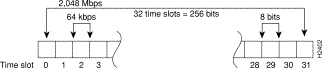
Time slot 0, or the first 8 bits, is reserved as overhead. The remaining 248 bits (31 frames with 8 bits each) are designated time slots 1 through 31. Time slot 16 is also designated as a framing slot when using framed mode.
The E1-G.703/G.704 interfaces support both framed (G.704) and unframed (G.703) modes of operation. Framed mode allows you to specify a bandwidth for the interface by designating a number of the 32 time slots for data, and reserving others for framing (timing). When you use framed mode, you must designate start and stop time slots; the slots within these boundaries are used for data, and the remaining slots are left idle.
For example, on an interface with framing set on time slots 1 through 8, the interface will carry data within the specified 8 frames, and frames 9 through 31 will remain idle. Because each time slot transmits at 64 kbps, the interface will operate at 512 kbps (8 frames x 64 kbps = 512 kbps).
By configuring 16 of the time slots to carry data and the remaining 16 to remain empty, you can essentially configure the interface for 1.024 Mbps. The FSIP inserts an idle pattern into unused time slots to identify them as overhead (unused for data). Only one contiguous time slot range can be used.
When you use unframed mode (G.703), you can configure time slot 16 to carry data and operate as any of the other slots. In framed mode (G.704), time slot 0 must be designated as a framing signal and time slot 16 can be configured for either data or framing. Unframed mode uses all 32 time slots for data (data is also called payload). None of the 32 time slots are used for framing signals. This allows each of the 32 time slots to transmit at 64 kilobits per second (kbps).
In PABX systems, time slot 16 is always left unused. By default, time slot 16 is not enabled for data in the FSIP E1-G.703/G.704 interface. By default, time slot 16 is not enabled for data in the E1-G.703/G.704 interface. The command ts16 overrides the default and enables time slot 16 to carry data. Nonsensical combinations of start and stop slots will be ignored, and the interface will be left unchanged. To restore the system default, use the no timeslot 16 command.
To enable framed operation, use the timeslot command; specify the start and stop slots, separated by a hyphen.
The following example shows the syntax of the timeslot command:
[no] timeslot 0/start-slot-31/stop_slot
The following example shows the timeslot command with a start slot of 1 and a stop slot of 13:
Router# timeslot 1-13
The no timeslot command restores the default of unframed mode.
Framed mode supports a 4-bit CRC, which you enable with a software command. CRC-4 is a 4-bit error checking technique that uses a calculated numeric value to perform an ongoing data integrity check and detect errors in transmitted data. The E1-G.703/G.704 interface supports CRC in framed mode only. By default, CRC-4 is not enabled. To enable CRC-4 on the E1 interface, specify the slot and port address of the interface followed by the command crc4. Press Ctrl-Z after altering the configuration and before exiting configuration mode.
In the example that follows, the first port on an FSIP in interface processor slot 0 is configured for CRC-4:
Router# configure terminal

Enter configuration commands, one per line. End with CNTL/Z.
Router(config)# interface serial 0/0

Router(config-if)# crc4

Ctrl-Z
To disable CRC and return an interface to the default of no CRC error checking, specify the interface and use the no crc4 command.
The E1-G.703/G.704 interface does not operate in the DTE and data communications equipment (DCE) modes that are typical of data communications interfaces. The E1-G.703/G.704 interface operates with either a line-recovered or an internal clock signal. The default is for a line clock signal that the interface recovers from the received data stream. The interface can also operate with an internal clock signal. The E1-G.703/G.704 port adapter generates the internal clock signal; the interface does not use the FSIP clock.
We recommend that you leave one port on each module shut down to avoid exceeding the 6.132 Mbps maximum for each module because the E1-G.703/G.704 interfaces operate at a default clock rate of 2.048 Mbps (E1 speed).
To specify the clock source, use the clock source {line | internal} command. To change the default and use the internal clock, use the clock source internal command. To return the interface to the default state, use the clock source line command. (The no clock source internal command also returns the interface to the default state.)
The following defines and describes the five alarms used with the E1-G.703/G.704 interface:
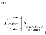
The E1-G.703/G.704 interface supports the same local loopback test as the other (data communications) FSIP interfaces. Loopback functions enable you to check the integrity of the physical data path between the FSIP and the E1 port adapter with the loopback command. The no loopback command disables all loopback tests on the interface.
You do not have to configure a clock signal on the interface before performing a loopback test because the E1-G.703/G.704 interface uses a default clock rate of 2.048 Mbps.
The loopback command tests the path between the FSIP and the interface port (without leaving the FSIP and port adapter). On the E1 port adapter, the loopback signal follows this path regardless of whether or not a cable is attached to the port.
Figure 25 shows the path of the loopback function.
Router# show controller cxbus


(additional displayed text omitted from this example)

FSIP 0, hardware version 3, microcode version 1.0
Interface 16- Serial0/0, electrical interface is RS-232 DTE
31 buffer RX queue threshold, 101 buffer TX queue limit, buffer size 1520
    Transmitter delay is 0 microseconds

Interface 17- Serial0/1, electrical interface is Universal (cable unattached)
31 buffer RX queue threshold, 101 buffer TX queue limit, buffer size 1520

(additional displayed text omitted from this example)
To change the electrical interface type or mode of a port online, you must replace the serial adapter cable and use software commands to restart the interface and, if necessary, reconfigure the port for the new interface.
At system startup or restart, the FSIP polls the interfaces and determines the electrical interface type of each port (according to the type of port adapter cable attached). However, it does not necessarily repoll an interface when you change the adapter cable online. To ensure that the system recognizes the new interface type, shut down and reenable the interface after changing the cable.
Perform the following steps to change the mode (DTE or DCE) or interface type (EIA/TIA-232, and so forth) of a port by replacing the adapter cable. First replace the cable, then shut down and bring up the interface with the new cable attached so that the system recognizes the new interface. If you are replacing a cable with one of the same interface type and mode, these steps are not necessary (simply replace the cable without interrupting operation).
Step 1 Locate and remove the adapter cable to be replaced.
Step 2 Connect the new cable between the FSIP port and the network connection. Tighten the thumbscrews at both ends of the cable to secure it in the ports.
Step 3 At the privileged level of the EXEC command interpreter, specify the port address, shut down the interface, and write the configuration to nonvolatile random-access memory (NVRAM). Add additional configuration commands as needed. Then exit from configuration mode by entering Ctrl-Z.
Router# configure terminal

Enter configuration commands, one per line. End with CNTL/Z.
Router(config)# int serial 0/1

Router(config-if)# shutdown

Ctrl-Z


Router# copy running-config startup-config
Step 4 Enter configuration mode again and bring the port back up:
Router# configure terminal

Enter configuration commands, one per line. End with CNTL/Z.
Router(config)# int serial 0/1

Router(config-if)# no shutdown

Router(config-if)# ^Z
These steps prompt the system to poll the interface and recognize the new interface immediately.
If you are changing the mode of the interface from DCE to DTE, you do not need to change the clock rate for the port. After you replace the DCE cable with a DTE cable and the system recognizes the interface as a DTE, it will use the external clock signal from the remote DCE device and ignore the internal clock signal that the DCE interface normally uses. Therefore, once you configure the clock rate on a port for either a DCE interface or loopback, you can leave the clock rate configured and still use that port as a DTE interface.
For additional descriptions of software configuration commands, refer to the appropriate publications listed in the section "If You Need More Information" on page 2.
The following summary describes how to use the show commands to verify that the new interfaces are configured correctly:
Step 1 Use the show version command to display the system hardware configuration. Ensure that the list includes the new interfaces.
Step 2 Display all the current interface processors and their interfaces with the show controllers cbus command. Verify that the new FSIP appears in the correct slot.
Step 3 Specify one of the new interfaces with the show interfaces serial slot/port command and verify that the first line of the display specifies the interface with the correct slot number. Also verify that the interface and line protocol are in the correct state: up or down.
Step 4 Display the protocols configured for the entire system and specific interfaces with the command show protocols. If necessary, return to configuration mode to add or remove protocol routing on the system or specific interfaces.
Step 5 Display the entire system configuration file with the show running-config command. Verify that the configuration is accurate for the system and each interface.
If an interface is down and you configured it as up, or if the displays indicate that the hardware is not functioning properly, ensure that the network interface is properly connected and terminated. If you still have problems, contact a service representative for assistance.
This completes the FSIP configuration procedure.
Cisco Connection Online (CCO) is Cisco Systems' primary, real-time support channel. Maintenance customers and partners can self-register on CCO to obtain additional information and services.
Available 24 hours a day, 7 days a week, CCO provides a wealth of standard and value-added services to Cisco's customers and business partners. CCO services include product information, product documentation, software updates, release notes, technical tips, the Bug Navigator, configuration notes, brochures, descriptions of service offerings, and download access to public and authorized files.
CCO serves a wide variety of users through two interfaces that are updated and enhanced simultaneously: a character-based version and a multimedia version that resides on the World Wide Web (WWW). The character-based CCO supports Zmodem, Kermit, Xmodem, FTP, and Internet e-mail, and it is excellent for quick access to information over lower bandwidths. The WWW version of CCO provides richly formatted documents with photographs, figures, graphics, and video, as well as hyperlinks to related information.
You can access CCO in the following ways:
For a copy of CCO's Frequently Asked Questions (FAQ), contact cco-help@cisco.com. For additional information, contact cco-team@cisco.com.
![]()
![]()
![]()
![]()
![]()
![]()
![]()
![]()
Posted: Mon Oct 14 13:40:08 PDT 2002
All contents are Copyright © 1992--2002 Cisco Systems, Inc. All rights reserved.
Important Notices and Privacy Statement.