|
|

Product Number UPG-RSP7000=
This document contains instructions for installing the 7000 Series Route Switch Processor (RSP7000) upgrade kit (UPG-RSP7000=) in the Cisco 7000 series routers: Cisco 7000 and Cisco 7010. This upgrade kit allows for 7500-series performance enhancements to the Cisco 7000 series routers. The RSP7000 upgrade kit includes the following components:
The RSP7000 upgrade kit requires that your Cisco 7000 series router is running Cisco Internetwork Operating System (Cisco IOS) Release 10.3(9), or later, Release 11.0(6), or later, or Release 11.1(1) or later.
 | Caution Using the RSP7000 upgrade kit in your Cisco 7000 series router might require that some currently installed interface processors be upgraded to specific, compatible hardware versions; otherwise, error messages and erratic system behavior might result.You can use the show diag command to see which interface processors in your system need this hardware upgrade. For a complete list of the potentially affected interface processors, their required hardware versions, and information on upgrading your affected interface processors, refer to the document Verifying Interface Processor Compatibility with the Cisco 7500 Series Investment Protection Program (IPP), Document Number 78-2077-xx, where xx refers to the latest version of this document. |
The sections in this document include the following:
Following are brief descriptions of the Cisco 7000 and Cisco 7010 routers, the RSP7000, and the RSP7000CI.
The Cisco 7000 is a seven-slot router chassis, which uses the new RSP7000. The Cisco 7000 provides up to five interface processor slots, and can accommodate the following CxBus-based interface processors: Fast Ethernet, Ethernet, Token Ring, Fiber Distributed Data Interface (FDDI), channel attachment, multichannel, serial, and so forth. The 7000 RSP and interface processors are keyed with guides on the backplane to prevent them from being fully inserted in the wrong slot.
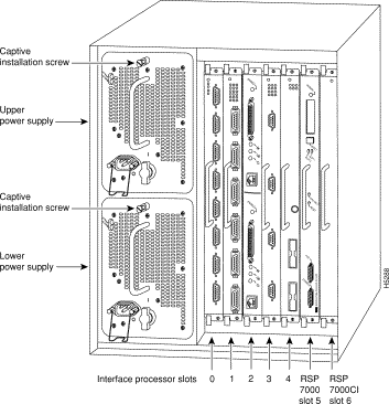
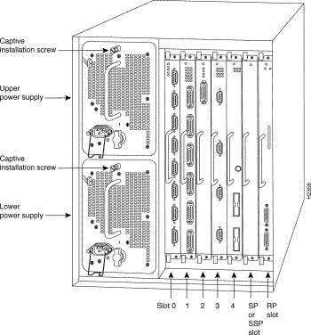
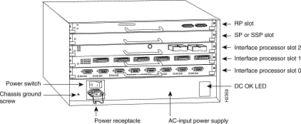
Figure 1 shows the rear of the Cisco 7000 router with the RSP7000 and RSP7000CI installed. In the Cisco 7000 series, two slots are reserved for the 7000 Route Switch Processor (RSP7000), which contains the system processor and performs packet switching functions, and the 7000 Chassis Interface (RSP7000CI) board, which contains all of the environmental monitoring functions for the Cisco 7000, when configured with the new 7000 RSP. The remaining slots (0 through 4) are for interface processor.
The Cisco 7010 is a five-slot chassis, which uses the new RSP7000 (and the RSP7000CI), and provides up to three interface processor slots that can accommodate the following CxBus-based interface processors: Fast Ethernet, Ethernet, Token Ring, Fiber Distributed Data Interface (FDDI), channel attachment, multichannel, serial, and so forth. The processor and interface processors are keyed with guides on the backplane to prevent them from being fully inserted in the wrong slot.
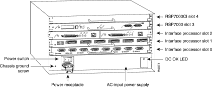
Figure 2 shows the rear of the Cisco 7010 router with the RSP7000 and RSP7000CI installed. In the Cisco 7010, slots 3 and 4 are reserved for the RSP7000, which contains the system processor and performs packet switching functions, and the RSP7000CI board, which contains all of the environmental monitoring functions for the Cisco 7010. The remaining three slots (slots 0 through 2) are for interface processors.
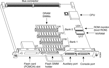
The RSP7000 is a new main system processor module for the Cisco 7000 series chassis. It combines all of the switched routing and high-speed switching functions of the separate Route Processor (RP) and Switch Processor (SP), which are used in the Cisco 7000 series routers, but with improved performance on a single processor module. The RSP7000 contains the central processing unit (CPU) and most of the memory components for the Cisco 7000 series chassis.
| Caution To prevent damage to the chassis slot and to the connector on the RSP7000, do not attempt to install the RSP7000 in any other slot but the chassis' 7000 RSP slot. Do not install the RSP7000 in the router's Route Processor (RP) slot. You must install the RSP7000 in the appropriate chassis' 7000 RSP slot. (See Figure 1 on page 2, for the Cisco 7000, or Figure 2 on page 3 for the Cisco 7010.) |
| Caution To prevent system problems, the RSP7000 must not be removed or installed with power ON to the chassis. The RSP7000 does not support online insertion and removal (OIR). |
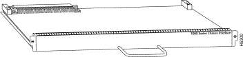
The RSP7000CI, shown in Figure 4, consists of a printed circuit board attached to a metal carrier. The RSP7000CI has no user-configurable jumpers or switches, and its faceplate contains no LEDs. The RSP7000CI is distinguishable only by the label on its faceplate, which reads 7000 Series Chassis Interface. (See Figure 4.) The RSP7000CI provides the environmental monitoring and power supply monitoring functions for the Cisco 7000 series chassis. The RSP7000CI isolates the CPU and system software from chassis-specific variations.
| Caution To prevent system problems, the RSP7000CI must not be removed or installed with power ON to the chassis. The RSP7000CI does not support online insertion and removal (OIR). You must install the RSP7000CI in the appropriate chassis' 7000 CI slot. (See Figure 1 on page 2, for the Cisco 7000, or Figure 2 on page 3 for the Cisco 7010.) |
The functions of the RSP7000CI are as follows:
Before you begin this installation, review the safety guidelines in this section to avoid injuring yourself or damaging the processor module.
Following are safety guidelines that you should follow when working with any equipment that connects to electrical power or telephone wiring.
Follow these basic guidelines when working with any electrical equipment:
Electrostatic discharge (ESD) damage, which can occur when electronic cards or components are improperly handled, results in complete or intermittent failures. Electromagnetic interference (EMI) shielding and connectors are integral components of the carrier. Use a preventive antistatic strap whenever handling a processor module.
Following are guidelines for preventing ESD damage:
| Caution For safety, periodically check the resistance value of the antistatic strap. The measurement should be between 1 and 10 megohms. |
The RSP7000 upgrade kit requires that your Cisco 7000 series router is running Cisco Internetwork Operating System (Cisco IOS) Release 10.3(9), or later, Release 11.0(6), or later, or Release 11.1(1) or later.
The show version and show hardware commands display the current hardware configuration of the router, including the system software version that is currently loaded and running. The show microcode command lists the bundled microcode (target hardware) version for each processor type. The show controller cbus command shows the microcode version you are running. (For complete descriptions of show commands, refer to the Router Products Configuration Guide and Router Products Command Reference publications.)
You can determine the current version of software or microcode stored in ROM either by removing the processor module and checking the ROM labels or by configuring the system to boot the system software or microcode from ROM, reloading the system, and using show commands to check the version that is loaded and running. Refer to the appropriate software documentation for complete configuration instructions and examples.
If the displays indicate that the required system software and microcode is not available in your system, contact a customer service representative for upgrade information. (Refer to the section "Customer Information Online" at the end of this document.)
You must install the RSP7000 in the appropriate chassis' 7000 RSP slot. (See Figure 1, on page 2, for the Cisco 7000, or Figure 2, on page 3, for the Cisco 7010.) For the RSP7000 to operate properly, the Cisco 7000 and Cisco 7010 chassis must also be configured with the RSP7000CI.
Following are the tools and equipment that you will need to complete this replacement:
If you have a Flash memory card installed in the PCMCIA slot of your RP, you must reformat it if you want to use it with your new RSP7000. Using the RSP7000, you cannot read data on the RP's Flash memory card, nor can you use it as bootable media. You must reformat the RP's Flash card before you can use it with the RSP7000. Flash memory cards formatted on the RP-based systems (7000 series routers) are formatted differently from Flash memory cards formatted on RSP-based systems (7500 series routers).
| Caution The formatting procedure erases all information on the Flash memory card. To prevent the loss of important data that might be stored on a Flash memory card, proceed carefully. If you want to save the data on a Flash memory card, copy the data to a server before you format the card. |
When you remove or install a processor module, be sure to use the ejector levers, which help to ensure that the processor module is fully inserted in the backplane or fully dislodged from it. Any processor module that is only partially connected to the backplane can halt the system.
Figure 5 on page 9 shows a detail of the ejector lever mechanism in a vertical position that is appropriate for the Cisco 7000. The processor module slots in the Cisco 7010 are oriented horizontally. When you simultaneously push the ejector levers inward (toward the carrier handle), the levers push the processor into the slot and ensure that the board connectors are fully seated in the backplane.
In the Cisco 7000, the RSP7000 must be installed in the 7000 RSP slot (slot 5) and the RSP7000CI must be installed in the 7000 CI slot (slot 6). In the Cisco 7010, the RSP7000 must be installed in the 7000 RSP slot (slot 3) and the RSP7000CI must be installed in the 7000 CI slot (slot 4).
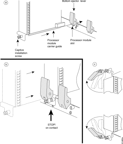
Figure 6 shows how to orient a card for installation in the Cisco 7000. During installation, refer to this illustration if you have a Cisco 7000.
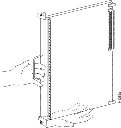
Figure 7 shows how to orient a card for installation in the Cisco 7010. During installation, refer to this illustration if you have a Cisco 7010.
This section describes the procedures for saving and retrieving the system configuration. Configuration information resides in two places when the router is operating: the default (permanent) configuration in NVRAM, and the running (temporary) memory in RAM. The default configuration always remains available; NVRAM retains the information even when the power is shut down. The current information is lost when if the system power is shut down. The current configuration contains all nondefault configuration information that you added with the configure command, the setup command facility, or by editing the configuration file.
The copy running-config startup-config command adds the current configuration to the default configuration in NVRAM, so that it will also be saved when power is shut down. Whenever you make changes to the system configuration, issue the copy running-config startup-config command to ensure that the new configuration is saved.
If you replace the RSP7000, you will also replace the entire configuration (NVRAM resides in socket U17 on the RSP7000). If you upload (copy) the configuration file to a remote server before removing the RSP7000, you can retrieve it later and write it into NVRAM on the new RSP7000. If you do not upload the configuration file, you will have to use the configure command or the setup command facility to reenter the configuration information after you install the new RSP7000. For complete descriptions of these commands and instructions for using them, refer to the appropriate software documentation.
This procedure is not necessary if you are temporarily removing an RSP7000 that you will reinstall; the lithium batteries will retain the configuration in memory until you replace the RSP7000 in the system.
This procedure requires privileged-level access to the EXEC command interpreter, which usually requires a password. Refer to the description that follows and contact your system administrator if necessary, to obtain access.
Before you use the configure command, you must enter the privileged level of the EXEC command interpreter with the enable command. The system prompts you for a password if one has been set.
The system prompt for the privileged level ends with a pound sign (#) instead of an angle bracket (>). At the console terminal, enter the privileged level as follows:
Router> enable


Password:
Step 2 Enter the password (the password is case sensitive). For security purposes, the password is not displayed.
Step 3 When you enter the correct password, the system displays the privileged-level system prompt (#) as follows:
Router#
The pound sign (#) at the system prompt indicates that you are at the privileged level of the EXEC command interpreter; you can now execute the EXEC-level commands that are described in the following sections.
Before you attempt to upload or retrieve a file from a remote host, ensure that the connection is good between the router and the remote server. The packet internet groper (ping) program sends a series of echo request packets to the remote device and waits for a reply. If the connection is good, the remote device echoes them back to the local device.
The console terminal displays the results of each message sent: an exclamation point (!) indicates that the local device received an echo, and a period (.) indicates that the server timed out while awaiting the reply. If the connection between the two devices is good, the system will display a series of exclamation points (! ! !) or [ok]. If the connection fails, the system will display a series of periods ( . . . ) or [timed out] or [failed].
To verify the connection between the router and a remote host, issue the ping command followed by the name or Internet Protocol (IP) address of the remote server, then press Return. Although the ping command supports configurable options, the defaults, including interface processor as the protocol, are enabled when you enter a host name or address on the same line as the ping command. For a description of the configurable options, refer to the appropriate software documentation.
The following example shows a successful ping:
Router# ping 1.1.1.1
Type escape sequence to abort.
Sending 5, 100-byte ICMP Echos to 1.1.1.1, timeout is 2 seconds:
!!!!!
Success rate is 100 percent (5/5), round-trip min/avg/max = 12/12/12 ms
Router#
The following example shows the results of a failed ping:
Sending 5, 100-byte ICMP Echos to 1.1.1.1, timeout is 2 seconds:
.....
Success rate is 0 percent (0/5)
Router#
If the connection fails, check the physical connection to the remote file server and verify that you are using the correct address or name, then ping the server again. If you are unable to establish a good connection, contact your network administrator or refer to the end of this document for instructions on contacting technical assistance.
Before you remove the RP and replace it with the RSP7000, you should upload the router's configuration file to a Trivial File Transfer Protocol (TFTP) file server, or else the configuration stored in the RP's Flash memory will be lost when you replace it. Before you upload (copy) the running configuration to the TFTP file server, ensure the following:
To store information on a remote host, enter the write network (or copy startup-config tftp) privileged EXEC command. The command prompts you for the destination host's address and a filename, then display the instructions for confirmation. When you confirm the instructions, the router sends a copy of the currently running configuration to the remote host. The system default is to store the configuration in a file called by the name of the router with -confg appended. You can either accept the default filename by pressing Return at the prompt, or enter a different name before pressing Return.
Follow these steps to upload (copy) the currently running configuration to a remote host:
Step 2 Use the ping command to check the connection between the router and the remote host.
Step 3 Issue the write term (or show running-config) command to display the currently running configuration on the terminal, and ensure that the configuration information is complete and correct. If it is not, use the configure command to add or modify the existing configuration. Then, issue the copy running-config startup-config command to save the retrieved configuration in NVRAM. (Refer to the appropriate software documentation for descriptions of the configuration options available for the system and individual interfaces, and for specific configuration instructions.)
Step 4 Issue the write net (or copy startup-config tftp) command. The EXEC command interpreter prompts you for the name or interface processor address of the remote host that is to receive the configuration file. (The prompt might include the name or address of a default file server.)
Router# write net

Remote host []?
Step 5 Enter the name or interface processor address of the remote host. In the following example, the name of the remote server is servername:
Router# write net

Remote host []? servername
Translating "servername"...domain server (1.1.1.1) [OK]
Step 6 The EXEC command interpreter prompts you for the name of the file that will contain the configuration. By default, the system appends -confg to the router's name to create the new filename. Press Return to accept the default filename, or enter a different name for the file before pressing Return. In the following example, the default is accepted:
Name of configuration file to write [Router-confg]?
Write file Router-confg on host 1.1.1.1? [confirm]
Writing Router-confg .....
Step 7 Before the router executes the copy process, it displays the instructions you entered for confirmation. If the instructions are not correct, enter n (no) then Return to abort the process. To accept the instructions, press Return or y then Return, and the system will begin the copy process. In the following example, the default is accepted:
Write file Router-confg on host 1.1.1.1? [confirm]
Writing Router-confg: !!!! [ok]
While the router copies the configuration to the remote host, it displays a series of exclamation points (! ! !) or periods (. . .). The !!!! and [ok] indicate that the operation is successful. A display of . . . [timed out] or [failed] indicates a failure, which would probably be due to a network fault or the lack of a writable, readable file on the remote file server.
Step 8 If the display indicates that the process was successful (with the series of ! ! ! and [ok]), the upload process is complete. The configuration is safely stored in the temporary file on the remote file server.
If the display indicates that the process failed (with the series of . . . as shown in the following example):
Writing Router-confg .....
your configuration was not saved. Repeat the preceding steps, or select a different remote file server and repeat the preceding steps.
After you upload the configuration file, proceed to "Removing the RP". If you are unable to copy the configuration to a remote host successfully, contact your network administrator or refer to the end of this document for instructions on contacting technical assistance.
After you install the new RSP7000, you can retrieve the saved configuration and copy it to NVRAM. To retrieve the configuration, enter configuration mode and specify that you will configure the router from the network. The system prompts you for a host name and address, the name of the configuration file stored on the host, and confirmation to reboot using the remote file.
You can access the router through a console terminal attached directly to the RSP7000 console port, or you can configure an interface port and Telnet to the router from a remote terminal.
Follow these steps to download (retrieve) the currently running configuration from a remote host:
Step 2 Use the ping command to verify the connection between the router and the remote host.
Step 3 At the system prompt, issue the configure network (or copy tftp startup-config) command and press Return to enter the configuration mode and specify that you will configure the system from a network device (instead of from the console terminal, which is the default).
Router# configure network
Step 4 The system will ask you to select a host or network configuration file. The default is host; press Return to accept the default.
Host or network configuration file [host]?
Step 5 The system prompts you for the interface processor address of the host. Enter the interface processor address or name of the remote host (the remote file server to which you uploaded the configuration file.
IP address of remote host [255.255.255.255]? 1.1.1.1
Step 6 The system prompts you for the name of the configuration file. When uploading the file, the default is to use the name of the router with the suffix -confg (router-confg in the following example). If you specified a different filename when you uploaded the configuration, enter the filename; otherwise, press Return to accept the default.
Name of configuration file [router-confg]?
Step 7 Before the system reboots with the new configuration, it displays the instructions you entered for confirmation. If the instructions are not correct, enter n (no) then press Return to cancel the process. To accept the instructions, press Return, or y then Return.
Configure using router-confg from 1.1.1.1? [confirm]
Booting router-confg from 1.1.1.1: ! ! [OK - 874/16000 bytes]
While the router retrieves and boots from the configuration on the remote host, the console display indicates whether or not the operation was successful. A series of !!!! and [OK] (as shown in the preceding example) indicates that the operation was successful. A series of . . . and [timed out] or [failed] indicate a failure (which would probably be due to a network fault or an incorrect server name, address, or filename). The following is an example of a failed attempt to boot from a remote server:
Booting Router-confg ..... [timed out]
Step 8 If the display indicates that the process was successful, proceed to the next step.
If the display indicates that the process failed, verify the name or address of the remote server and the filename, and repeat the preceding steps. If you are unable to retrieve the configuration, contact your network administrator or refer to the end of this document for instructions on contacting technical assistance.
Step 9 Issue the write term (or show running-config) command to display the currently running configuration on the terminal. Review the display and ensure that the configuration information is complete and correct. If it is not, verify the filename and repeat the preceding steps to retrieve the correct file, or use the configure command to add or modify the existing configuration. (Refer to the appropriate software documentation for descriptions of the configuration options available for the system and individual interfaces and specific configuration instructions.).
Step 10 When you have verified that the currently running configuration is correct, issue the copy running-config startup-config command to save the retrieved configuration in NVRAM. Otherwise, the new configuration will be lost if you restart the system. This completes the procedure for downloading (retrieving) the configuration file.
Following is a overview of the procedures for installing the RSP7000 upgrade kit in the Cisco 700 chassis.
To install the RSP7000 upgrade kit, the following overview indicates the procedures that are required, after the router is powered down:
1. Turn off power to the chassis.
| Caution To prevent system problems, turn off power to your chassis before proceeding with the RSP7000 upgrade procedures. The RP, SP (or SSP), RSP7000, and RSP7000CI do not support online insertion and removal (OIR), so power to the chassis must be turned OFF before attempting to remove or install these processor modules. |
2. Remove the RP from slot 6 of the Cisco 7000 or slot 4 of the Cisco 7010.
3. Install the RSP7000CI in the 7000 CI slot of your chassis.
4. Remove the SP (or SSP) from slot 5 of the Cisco 7000 or slot 3 of the Cisco 7010.
5. Install the RSP7000 in the 7000 RSP slot of your chassis.
6. Power on the router for an installation check.
Follow these steps to remove the RP:
| Caution You must shut down the system before removing the RP, which is a required system component. Removing a RP while the system is operating will cause the system to shut down or crash and might damage or destroy memory files. |
Step 2 Slip on an antistatic strap and connect the equipment end of the strap to a captive installation screw on an installed interface processor, or to any unfinished chassis surface.
Step 3 Disconnect any devices that are attached to the console or auxiliary ports on the RP.
Step 4 Locate the RP in your chassis. The SP (or SSP) is installed in slot 5 in the Cisco 7000 (see Figure 8) or slot 3 in the Cisco 7010 (see Figure 9).
Step 5 Use a screwdriver (number 2 Phillips or 3/16-inch flat-blade) to loosen the two captive installation screws on the RP. (See Figure 5a on page 9.)
Step 6 Place your thumbs on the ends of each of the ejectors and simultaneously pull them both outward, away from the carrier handle (in the direction shown in Figure 5c on page 9) to release the carrier from the slot and to dislodge the RP from the backplane.
Step 7 Grasp the handle with one hand and pull the RP straight out of the slot, keeping your other hand under the carrier to guide it. Keep the carrier parallel to the backplane. Avoid touching the board or any connector pins.
Step 8 Place the removed RP on an antistatic mat or foam. If you plan to return the RP to the factory, immediately place it in an antistatic bag to prevent ESD damage.
This completes the RP removal procedure.
The RSP7000CI is keyed for installation only in the RSP7000CI slot (slot 6 in the Cisco 7000, see Figure 1, and slot 4 in the Cisco 7010, see Figure 2).
| Caution To prevent damage to the chassis slot and to the connector on the RSP7000CI, do not attempt to install the RSP7000CI in any other slot but the chassis' 7000 CI slot. Do not install the RSP7000CI in the router's Switch Processor (SP) slot. You must install the RSP7000CI in the 7000 CI slot. |
Follow these steps to install an RSP7000CI:
Step 2 Place the back of the RSP7000CI in the 7000 CI slot, and align the notches along the edge of the carrier with the grooves in the slot. (See Figure 5a on page 9.)
Step 3 While keeping the RSP7000CI parallel to the backplane, carefully slide the carrier into the 7000 CI slot until the RSP7000CI faceplate makes contact with the ejector levers, then stop. (See Figure 5b on page 9.)
Step 4 Using the thumb and forefinger of each hand to pinch each ejector, simultaneously push both ejectors inward (toward the handle) until they parallel to the faceplate. (See Figure 5c on page 9.)
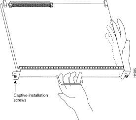
Step 5 Use a screwdriver (number 2 Phillips or 3/16-inch flat-blade) to tighten the captive installation screws on the ends of the RSP7000CI. (See Figure 5a on page 9.)
Tighten the two captive screws on the RSP7000CI faceplate to prevent the RSP7000CI from becoming partially dislodged from the backplane and to ensure proper EMI shielding. (These screws must be tightened to meet EMI specifications.)
This completes the RSP7000CI installation procedure.
Follow these steps to remove the SP (or SSP):
| Caution You must shut down the system before removing the SP (or SSP), which is a required system component. Removing an SP (or SSP) while the system is operating will cause the system to shut down or crash and might damage or destroy memory files. |
Step 2 Locate the SP (or SSP) in the your chassis. The SP (or SSP) is installed in slot 5 in the Cisco 7000 or slot 3 in the Cisco 7010.
Step 3 Use a screwdriver (number 2 Phillips or 3/16-inch flat-blade) to loosen the two captive installation screws on the SP (or SSP). (See Figure 5a on page 9.)
Step 4 Place your thumbs on the ends of each of the ejectors and simultaneously pull them both outward, away from the carrier handle (in the direction shown in Figure 5c on page 9) to release the carrier from the slot and to dislodge the RP from the backplane.
Step 5 Grasp the handle with one hand and pull the RP straight out of the slot, keeping your other hand under the carrier to guide it. (See Figure 6 or Figure 7, depending on your chassis model.) Keep the carrier parallel to the backplane. Avoid touching the board or any connector pins.
Step 6 Place the removed SP (or SSP) on an antistatic mat or foam. If you plan to return the board to the factory, immediately place it in an antistatic bag to prevent ESD damage.
This completes the SP (or SSP) removal procedure.
The RSP7000 is keyed for installation only in the 7000 RSP slot (slot 5 in the Cisco 7000, see Figure 1, and slot 3 in the Cisco 7010, see Figure 2).
Follow these steps to install the RSP7000:
Step 2 Place the back of the RSP7000 in the 7000 RSP slot, and align the notches along the edge of the carrier with the grooves in the slot.
| Caution To prevent damage to the backplane, you must install the RSP7000 in slot 5 of the Cisco 7000 or slot 3 of the CIsco 7010. (See Figure 1 on page 2 or Figure 2 on page 3.) The slots are keyed for correct installation. Forcing the 7000 RSP into a different slot can damage the backplane and the RSP7000. |
Step 3 While keeping the RSP7000 parallel to the backplane, carefully slide the carrier into the 7000 RSP until the RSP7000 faceplate makes contact with the ejector levers, then stop. (See Figure 5b on page 9.)
Step 4 Using the thumb and forefinger of each hand to pinch each ejector, simultaneously push both ejectors inward (toward the handle) until they parallel to the faceplate. (See Figure 5c on page 9.)
Step 5 Use a screwdriver (number 2 Phillips or 3/16-inch flat-blade) to tighten the captive installation screws on the ends of the RSP7000. (See Figure 5a on page 9.)
Tighten the two captive screws on the RSP7000 faceplate to prevent the RSP7000 from becoming partially dislodged from the backplane and to ensure proper EMI shielding. (These screws must be tightened to meet EMI specifications.)
Step 6 Connect the console terminal to the console port and any auxiliary devices to the auxiliary port on the RSP7000.
Step 7 Ensure that the console terminal is turned on.
Use the following sections to verify that the RSP7000 upgrade kit operates properly in your Cisco 7000 series router.
If you had a Flash memory card installed in the PCMCIA slot of your RP, you must reformat it if you want to use it with your new RSP7000. You cannot read data on the RP's Flash memory card, or use it as bootable media, unless you reformat it. Flash memory cards formatted on the RP-based systems (7000 series routers) are formatted differently from Flash memory cards formatted on RSP-based systems (7500 series and RSP7000-based routers).
| Caution The formatting procedure erases all information on the Flash memory card. To prevent the loss of important data that might be stored on a Flash memory card, proceed carefully. If you want to save the data on a Flash memory card, copy the data to a server before you format the card, then retrieve the date after the card is reformatted. |
Use the following procedure to format a new Flash memory card:
Step 2 To format the Flash memory card, use the format slot0: (or format slot1:) command as follows. (Use only Intel Series 2+ Flash memory cards.)
Router# format slot0:

All sectors will be erased, proceed? [confirm]
Enter volume id (up to 30 characters): MyNewCard

Formatting sector 1
Format device slot0 completed
Router#
The new Flash memory card is now formatted and ready to use.
Use the following information to verify that the RSP7000 operates properly. When you turn the system power back on, verify that the system boots and resumes normal operation.
Perform the following steps to verify that the RSP7000 is installed and functioning properly:
Step 2 Observe the RSP7000 LEDs. While the system initializes, the yellow boot error LED on the RSP7000 stays on, then goes off when the boot is complete. As the RSP7000 initializes each interface processor, the status LEDs on each interface processor go on and off in irregular sequence.
Step 3 Verify that the console terminal displays the system banner and startup screen as the system restarts. The display should look similar to the following:
GS Software (RSP-K), Version 10.3(9), RELEASED SOFTWARE
Copyright (c) 1986-1995 by cisco Systems, Inc.
Compiled Wed 10-May-95

System Bootstrap, Version 5.3(9)

Current date and time is Sat 5-13-1995 21:38:35
Boot date and time is Thur 5-11-1995 15:32:28
[displayed text omitted from this example]
Step 4 After the system boots the software and initializes the interface processors (approximately 30 seconds for systems with 16 MB of DRAM, and approximately 2 minutes for systems with 64 MB of DRAM), verify that the RSP7000 LEDs are in the following states:
Step 5 Verify that all the enabled LEDs (on the interface processors) are on.
When you have verified all the conditions in Steps 2 through 5, the installation is complete.
If you replaced the RSP7000 and saved your configuration file to a remote server before doing so, proceed to the section "Downloading (Retrieving) the Configuration File". If you replaced the RSP7000 and did not save the configuration, use the configure command or the setup command facility to reenter the configuration information. Refer to the appropriate software documentation for command descriptions and instructions for using them.
An error condition exists if no LEDs go on at power up or after initialization, or if the boot error or CPU halt LEDs go on and remain on. If this happens, refer to the troubleshooting information in the Cisco 7000 Hardware Installation and Maintenance or Cisco 7010 Hardware Installation and Maintenance publication to try to isolate the problem, or contact a service representative for assistance.
This completes checking the RSP7000 installation
Verify that the RSP7000 is installed in the chassis' 7000 RSP slot (see Figure 1 on page 2 or Figure 2 on page 3). Verify that the RSP700CI is installed in the chassis' 7000 CI slot (see Figure 1 on page 2 or Figure 2 on page 3), and that the captive installation screws on both processor modules are tightened.
Using the RSP7000CI and the temperature sensors on the RSP7000, the system displays warning messages on the console if chassis interface-monitored parameters exceed a desired threshold or if a blower failure occurs. You can retrieve and display environmental status reports with the show environment, show environment all, show environment last and show environment table commands. Parameters are measured and reporting functions are updated every 60 seconds. Use these show commands to verify that the RSP7000CI installation was successful. A brief description of each of these commands follows.
The show environment command display reports the current environmental status of the system. The report displays parameters that are out of the normal values. No parameters are displayed if the system status is normal. The example that follows shows the display for a system in which all monitored parameters are within Normal range.
Following is sample output of the show env command:
Router# show env


All measured values are normal
If the environmental status is not normal, the system reports the worst-case status level in the last line of the display.
RSP7000#sho env last

  CI(6) Inlet        previously measured at 22C/71F
    CI(6) Hotpoint     previously measured at 31C/87F
      CI(6) Exhaust      previously measured at 23C/73F
        +12 Voltage        previously measured at 12.12
          +5 Voltage         previously measured at 5.13
            -12 Voltage        previously measured at -11.84
              +24 Voltage        previously measured at 24.06

RSP7010#sho env last

  CI(4) Inlet        previously measured at 23C/73F
  CI(4) Hotpoint     previously measured at 35C/95F
  CI(4) Exhaust      previously measured at 25C/77F
  +12 Voltage        previously measured at 12.31
  +5 Voltage         previously measured at 5.17
  -12 Voltage        previously measured at -11.89
  +24 Voltage        previously measured at 23.78
The show environment table command displays the temperature and voltage thresholds for each of the three RSP7000 temperature sensors, for each monitored status level: low critical, low warning, high warning, and high critical. The slots in which the RSP7000 can be installed are indicated in parentheses (2 and 3). Also listed are the shutdown thresholds for the processor boards and power supplies. An example of the show env table command follows for both the Cisco 7000 and Cisco 7010:
RSP7000#sho env table

Sample Point      LowCritical    LowWarning     HighWarning
HighCritical
CI(6) Inlet                       44C/111F       50C/122F
CI(6) Hotpoint                    54C/129F       60C/140F
CI(6) Exhaust
+12 Voltage       10.90          11.61          12.82          13.38
+5 Voltage        4.61           4.94           5.46           5.70
-12 Voltage       -10.15         -10.76         -13.25         -13.86
+24 Voltage       20.38          21.51          26.42          27.65
2.5 Reference                    2.43           2.51
Shutdown power supplies at   70C/158F

RSP7010#sho env table

Sample Point      LowCritical    LowWarning     HighWarning
HighCritical
CI(4) Inlet                                     44C/111F       50C/122F
CI(4) Hotpoint                                  54C/129F       60C/140F
CI(4) Exhaust
+12 Voltage       10.90          11.61          12.82          13.38
+5 Voltage        4.61           4.94           5.46           5.70
-12 Voltage       -10.15         -10.76         -13.25         -13.86
+24 Voltage       20.38          21.51          26.42          27.65
2.5 Reference                    2.43           2.51
Shutdown power supplies at   70C/158F
The show environment all command displays an extended report that includes the arbiter type, backplane type, power supply type (AC or DC), wattage and status, the number and type of intermittent power failures (if any) since the system was last powered on, and the currently measured values at the RSP7000 temperature sensors and the power supply voltages. An example of the show env all command follows for both the Cisco 7000 and Cisco 7010:
RSP7000#sho env all

 Arbiter type 1, backplane type 70x0 (id 5)
 Power supply #1 is 700W (id 2), power supply #2 is removed (id 3)
 Active fault conditions: none
 Active trip points: none

                         0123456
             Dbus slots:  X   X

              card     inlet       hotpoint     exhaust
               CI(6)   21C/69F      30C/86F      22C/71F

               Shutdown temperature source is 'hotpoint' on CI(6),
               requested CI(6)

               +12V measured at 12.12
                +5V measured at 5.13
                -12V measured at -11.84
                +24V measured at 24.06
                +2.5 reference is 2.49
RSP7010#sho env all

 Arbiter type 1, backplane type 70x0 (id 5)
 Power supply #1 is 600W AC (id 1)
 Active fault conditions: none
 Active trip points: none

                         01234
             Dbus slots:  X X

              card     inlet       hotpoint     exhaust
               CI(4)   22C/71F      34C/93F      24C/75F

               Shutdown temperature source is 'hotpoint' on CI(4),
               requested CI(4)

               +12V measured at 12.31
                +5V measured at 5.17
                -12V measured at -11.89
                +24V measured at 23.78
                +2.5 reference is 2.49
If after several attempts, any component does not appear to be functioning properly, or if you experience trouble with the installation (for instance, if the holes in the board do not align with the backplane holes), contact a service representative or the Technical Assistance Center (TAC). (For the TAC phone number and email address, refer to the note at the end of this document.
This completes checking the RSP7000CI installation, and also completes the RSP7000 upgrade kit installation.
Cisco Information Online (CIO), is Cisco Systems' primary, real-time support channel. Maintenance customers and partners can self-register on CIO to obtain additional content and services.
Available 24 hours a day, 7 days a week, CIO provides a wealth of standard and value-added services to Cisco's customers and business partners. CIO services include product information, software updates, release notes, technical tips, the Bug Navigator, configuration notes, brochures, descriptions of service offerings, and download access to public and authorized files.
CIO serves a wide variety of users through two interfaces that are updated and enhanced simultaneously—a character-based version and a multimedia version that resides on the World Wide Web (WWW). The character-based CIO (called "CIO Classic") supports Zmodem, Kermit, Xmodem, FTP, Internet e-mail, and fax download options, and is excellent for quick access to information over lower bandwidths. The WWW version of CIO provides richly formatted documents with photographs, figures, graphics, and video, as well as hyperlinks to related information.
You can access CIO in the following ways:
http://www.cisco.com
cio.cisco.com
For a copy of CIO's Frequently Asked Questions (FAQ), contact cio-help@cisco.com. For additional information, contact cio-team@cisco.com.
tac@cisco.com. To obtain general information about Cisco Systems, Cisco products, or upgrades, contact 800 553-6387, 408 526-7208, or cs-rep@cisco.com.
![]()
![]()
![]()
![]()
![]()
![]()
![]()
![]()
Posted: Mon Feb 12 14:02:28 PST 2001
All contents are Copyright © 1992--2001 Cisco Systems, Inc. All rights reserved.
Important Notices and Privacy Statement.