|
|

The 5-slot Cisco 7010, the newest router/bridge in the Cisco 7000 series, provides high reliability, availability, serviceability, and performance. Cisco 7000 series routers support multiprotocol, multimedia routing and bridging with a wide variety of protocols and any combination of Ethernet, Fast Ethernet, Token Ring, FDDI, serial, multichannel channel attachment, and HSSI media. Network interfaces reside on modular interface processors, which provide a direct connection between the high-speed Cisco Extended Bus (CxBus) and the external networks.
Online insertion and removal (OIR) allows you to add, replace, or remove interface processors without interrupting the system power or entering any console commands. Environmental monitoring and reporting functions enable you to maintain normal system operation by resolving adverse environmental conditions prior to loss of operation. If conditions reach critical thresholds, the system shuts down to avoid equipment damage from excessive heat or electrical current. Downloadable software and microcode, which is used for most software and microcode upgrades, allows you to load new images into Flash memory remotely, without having to physically access the router, for fast, reliable upgrades.
This chapter provides physical and functional overviews to familiarize you with your new router. It contains physical descriptions of the system hardware and major components, and functional descriptions of hardware-related features. Descriptions and examples of software commands appear only when they are necessary for installing or maintaining the system hardware. For complete command descriptions and instructions, refer to the Router Products Configuration Guide and Router Products Command Reference, which are available on UniverCD.
Following is a list of acronyms that identify the system components and features:
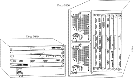
The Cisco 7010 is the entry-level model in the Cisco 7000 series product line, which currently includes the 7-slot Cisco 7000 and the 5-slot Cisco 7010. Both models use the same RP, SP (or SSP), and interface processors; all processor modules are interchangeable between the two models. The Cisco 7000 provides five interface slots and offers a second modular power supply for redundant power. The Cisco 7010 provides three interface slots and the same performance as the Cisco 7000 at a lower cost. Table 1-1 shows a comparison of the two Cisco 7000 series products. Figure 1-1 shows the interface processor end of both models.
| Feature | Cisco 7010 | Cisco 7000 |
|---|---|---|
Interface slots available | 5 horizontal processor slots; 3 interface processor slots | 7 vertical processor slots; 5 interface processor slots |
Maximum interface ports | 24 | 40 |
Redundant power | Not available | Available with optional second power supply |
Dimensions (H x W x D) | 10.5 x 17.5 x 17" (26.67 x 44.45 x 43.18 cm) | 19.25 x 17.5 x 25.1" (48.90 x 44.45 x 63.75 cm) |
Weight, fully configured | ~70 lb (31.75 kg) | ~147 lbs. (66.68 kg) |
Radiated acoustic noise (bystander position) | Approximately 46 dBa (fans at normal speed) or 58 dBa (fans at high speed) | Approximately 62 dBa |
Software Release 9.17(6) or later | Software Release 9.17(1) or later |
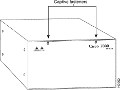
The front, or noninterface processor end, of the Cisco 7010 is a removable cover panel that is secured with two captive slotted fasteners. (See Figure 1-2.) Removing the cover panel provides access to the three internal components: the arbiter, power supply, and fan tray.
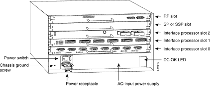
The interface processor end of the router contains the five-processor slots, the AC-input receptacle, the power switch, and a power status LED indicator. The processor slots contain the RP, SP (or SSP), and up to three interface processors. When viewing the router from the interface processor end, the RP is in the top slot (the RP slot), and the SP (or SSP) is in the slot directly below the RP. The remaining three slots are numbered from the bottom up beginning with slot 0 (the bottom slot) through 2 (the center slot).
The three interface processor slots support any combination of network interface types: Ethernet, Token Ring, FDDI, serial, multichannel channel attachment, and HSSI. The RP, SP (or SSP), and interface processors are keyed with guides on the backplane to prevent them from being fully inserted in the wrong slot.
Figure 1-3 shows the interface processor end of a Cisco 7010 with an AC-input power supply.
The RP, SP (or SSP), and interface processors (collectively referred to as processor modules in this manual) slide into the processor slots in the rear of the router and connect directly to the backplane; there are no internal cables to connect. Spring-loaded ejector levers help to ensure that a processor module is either fully connected to the backplane or fully disconnected from it. Captive installation screws, one at each end of the interface processor faceplate, also ensure proper seating in the slot and prevent the processor module from disengaging from the backplane connectors. (During operation, the system will hang if the connection between the processor module connector and any of the backplane pins is interrupted.) Empty slots contain a blank interface processor filler (the metal interface processor carrier without a board, LEDs, or connectors) to maintain proper airflow through the chassis.
One 550-watt (W) AC-input power supply or one 600W DC-input power supply is standard equipment in the router.
The Cisco 7010 operates as either a tabletop or rack-mounted unit. A rack-mount kit is standard equipment that is included with all chassis. The kit provides the hardware needed to mount the router in a standard 19-inch equipment rack, or in a variety of other equipment rack configurations. When the router is not mounted in a rack, place it on a table or on a sturdy platform. Do not stack the router with any other equipment or place it directly on a floor. For clearance requirements and rack installation considerations, refer to the section "Site Environment" in the chapter "Preparing for Installation."
Table 1-2 lists the Cisco 7010 physical specifications and power requirements.
| Description | Specification |
|---|---|
High-speed backplane | 533-Mbps CxBus, 3 interface processor slots plus RP, SP, and SSP slots |
10.5 x 17.5 x 17.0" (26.67 x 44.45 x 43.18 cm) | |
Chassis only (including power supply and fan array): 46 lb (20.87 kg) | |
550W maximum configuration, 540W typical of maximum configuration with AC input | |
715W (2440 Btu/hr) | |
Input voltage | 100 to 240 VAC, wide input with power factor corrector (PFC) |
Power distribution | 70A maximum @ +5 VDC, 15A maximum @ +12 VDC, 3A maximum @ -12 VDC, 5A maximum @ +24 VDC |
50 to 60 Hz | |
9A maximum at 100 VAC, 4A maximum at 240 VAC at 600W | |
DC-input voltage | -40 volts DC (VDC) minimum in North America (-56 VDC in Europe) |
DC voltages supplied and maximum, steady-state current ratings | +5.2 VDC @ 75 amps (A) |
DC-input power supply hold-up time specification | 10 milliseconds (ms) of output after the input has been interrupted |
DC-input power supply cable guage | 10 American Wire Guage (AWG) |
Side-to-side through chassis by variable-speed, 6-fan array | |
32 to 104° F (0 to 40° C) | |
Nonoperating temperature | -4 to 149° F (-20 to 65° C) |
10 to 90%, noncondensing | |
Safety: UL 1950, CSA 22.2-950, EN60950, EN41003, AUSTEL TS001, AS/NZS 3260 |
For a chassis footprint, additional dimensions, and clearance requirements for the router perimeter, refer to the section "Site Requirements" in the chapter "Preparing for Installation."
The main internal components in the Cisco 7010 are the arbiter, power supply, fan tray, and backplane, all of which are located in the noninterface processor end of the router. The power supply and fan tray are available as spares. The arbiter is categorized as a field-replaceable unit (FRU), which means that it can only be replaced by a Cisco-certified technician. Note that the backplane is not a spare or an FRU.
The power supply, which rests on the interior chassis floor, provides DC voltages to the system components. The six individual fans on the fan tray move cooling air through the chassis interior to prevent components from overheating. The backplane contains the data busses for information exchange and distributes power throughout the system. The following sections describe the FRUs and other major system components.
Figure 1-4 shows the components in their normal operating positions.
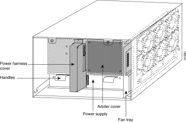
The arbiter, which arbitrates traffic on the CxBus and generates the CxBus clock, is a printed circuit board that is mounted to the front (noninterface processor side) of the backplane. (See Figure 1-4.) The arbiter arbitrates traffic across the CxBus by prioritizing access requests from interface processors to ensure that each request is processed, and to prevent any interface processor from jeopardizing the CxBus and interfering with the ability of the other interface processors to access the SP (or SSP) and RP. The arbiter provides the following services for the system:
Slots in the arbiter cover allow secondary airflow and natural convection to cool the arbiter, which is outside the primary path of cooling air through the chassis. The chapter "Maintenance" provides replacement instructions for the arbiter.
The Cisco 7010 comes equipped with one 550W, AC-input power supply (shown in Figure 1-4) or one 600W, DC-input power supply. The AC-input power supply operates on AC-input power and supplies DC power to the internal components. The DC-input power supply operates on DC input power and supplies DC power to the internal components. Table 1-2 lists the acceptable AC-input and DC-input ranges and the internal operating DC voltages and current levels.
At the noninterface processor end of the router, two handles on the power supply provide grip points for pulling the power supply out of the chassis. (See Figure 1-4.) Two Phillips-head screws secure the power supply to the chassis interior. The power supply delivers DC power to the internal components through a wiring harness that plugs into a polarized receptacle to the noninterface processor side of the backplane. An aluminum cover shields the harness and power connection. The backplane distributes the DC voltages to the fan tray, arbiter, and interface processor bus connectors.
The AC power receptacle (or DC-input terminal block), power on/off switch, and status LED are on the interface processor end of the power supply. A modular power cord connects the AC power supply to the site power source. A cable retention clip on the power supply AC receptacle prevents the cable from being pulled out accidentally. The DC-input is supplied by a three-lead, 10 AWG cable you provide. Strain relief consists of nylon cable ties that you also provide.
The power switch turns the power supply on and starts the system. To the left of the power switch and receptacle cutout is a ground screw that provides a chassis ground connection for ESD-preventive equipment or a grounding wire. Figure 1-5 shows the AC power supply from the interface processor end of the router.
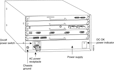
On the AC-input and DC-input power supplies, the green DC OK LED indicates the status of the power supply and internal DC voltages. The DC OK LED stays on when all of the following conditions are met:
If the AC or DC source power or any of the internal DC voltages exceeds allowable tolerances, the DC OK LED goes off and the system environmental monitor messages indicate the line that is out of tolerance. Because the RP (which uses +5, +12, -12 VDC), and the fan tray (which uses +24 VDC) are both required for operation, the system will probably shut down if any internal voltages reach an out-of-tolerance state.
Inside the AC-input or DC-input power supply, two small fans draw cooling air through the power supply interior. The air flows in one side of the supply and out the other side, following the same direction as the chassis cooling air. (See Figure 1-6.)
In addition to the environmental monitoring performed by the system software, the power supply monitors its own temperature and internal voltages. If the supply detects an overvoltage, or overtemperature condition, it shuts down to avoid damage to the power supply or other system components. For a description of power-supply shutdown conditions and thresholds, refer to the section "Environmental Monitoring and Reporting Functions" in this chapter.
The AC-input and DC-input power supplies are available as spares for immediate onsite replacement in case the existing power supply fails. The chapter "Maintenance" provides power supply replacement instructions. In addition, detailed, up-to-date instructions are included with all spares when they are shipped from the factory.
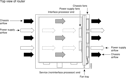
An array of six individual fans draw cooling air through the chassis interior to maintain an acceptable operating temperature for the internal components. The fan tray comprises the six fans and a printed circuit board (with the control circuits) mounted on a metal plate. (See Figure 1-4.) The fan tray slides into the right side of the chassis from the noninterface processor end of the router. The fans draw air in through the inlet vents on the opposite side of the chassis, across the processor modules and other internal components, and out through the exhaust vents adjacent to the fan tray. Figure 1-6 shows the airflow path. The sides of the chassis must remain unobstructed to ensure adequate airflow and prevent overheating inside the chassis. (See the section "Site Requirements" in the chapter "Preparing for Installation.")
A fan control board on the fan tray monitors and controls the operation of the variable-speed fans. The variable-speed feature enables quieter operation by allowing the fans to operate at less than maximum speed when doing so provides adequate cooling air to maintain an acceptable operating temperature inside the chassis. A temperature sensor on the RP monitors the internal air temperature. When the ambient air temperature is within the normal operating range, the fans operate at the slowest speed, which is 55 percent of the maximum speed. If the temperature inside the chassis exceeds the normal range, the fan control board increases the fan speed to provide additional cooling air to the internal components. If the temperature continues to rise, the fan control board linearly increases the fan speed until the fans reach full speed (100 percent). If the internal temperature exceeds the specified threshold, the system environmental monitor shuts down all internal power to prevent equipment damage from excessive heat.
All six fans in the array must be operational. If the system detects a failed or failing fan, it will display a warning message on the console screen. If the condition is not corrected within two minutes, the entire system will shut down to avoid an overtemperature condition and shutdown. For specific thresholds and message descriptions, refer to the section "Environmental Monitoring and Reporting Functions" in this chapter and to the section "Troubleshooting the Cooling Subsystem" in the chapter "Troubleshooting the Installation."
The fan tray is available as a spare. Individual fans are not field-replaceable; if a single fan fails, you must replace the fan tray. The chapter "Maintenance" provides fan tray replacement instructions.
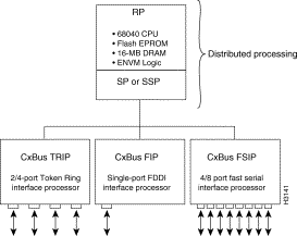
The high-speed CxBus transfers information at 533 Mbps. Figure 1-7 shows the basic system architecture. The RP, which contains the system processor, and the SP provide distributed processing and control for the interface processors. The SP (or SSP) controls communication between interface processors (interface processor-to-interface processor) and the system processor (interface processor-to-processor).
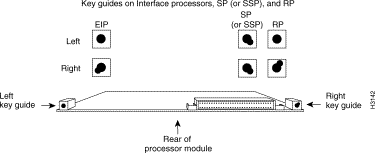
The backplane slots are keyed so that the processor modules can be installed only in the slots designated for them. Keys on the backplane fit into two key guides on each module. (See Figure 1-8.) Although the RP, SP, and SSP each use unique keys, all three interface processor slots use the same key, so you can install an interface processor in any interface processor slot.
 | Caution When installing an RP, SP, SSP, or interface processor, ensure that you are installing it in the appropriate slot to avoid damaging the key guides or the backplane. |
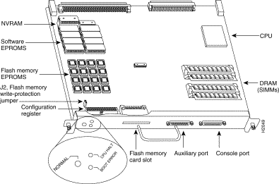
The RP, shown in Figure 1-9, is the main system processor in the router. The RP contains the system central processing unit (CPU), the system software, and most of the system memory components, and it maintains and executes the management functions that control the system. The RP contains the following components:
In addition to the preceding system components, the RP contains and executes the following management functions that control the system:
The RP must be installed in the top processor slot, which is labeled RP.
Table 1-3 lists the functions of the various types of memory on the RP, and Figure 1-9 shows the locations of each.
| Memory Type | Size | Quantity | Description | Location |
|---|---|---|---|---|
4 Mb2 | 8 | 4-Mb EPROMs | ROM1-ROM8 (see the chapter "Maintenance") | |
16 MB | 4 | 4-MB SIMMs | SIMMS sockets U35, U36, U58, U59 | |
128 KB | 1 | 128 KB | U120 | |
Flash memory | 4 MB | 16 | 256-KB Flash memory components | U14-U17, U27-U30, U45-U48, U60-63 |
Flash memory card3 | 8 or 16 MB | 1 | PCMCIA Flash memory card | Flash memory card slot on faceplate |
EEPROM | - | 1 | Board-specific information, address allocator | U108 |
Eight EPROM components contain the default and bootstrap system software. The downloadable system software and microcode feature, which the Cisco 7000 series supports for most upgrades, allows you to remotely download, store, and boot from a new image.
EPROMs for Software Release 9.17(7), and later, also contain the latest microcode version in compressed form for each interface processor. At system startup, an internal system utility scans for compatibility problems between the installed interface processor types and the bundled microcode images, then decompresses the images into running, random-access memory (RAM). The bundled microcode images then function the same as images loaded from the microcode EPROMs.
It is unlikely that you will ever need to replace the default system software EPROMs. If replacement is necessary in the future, refer to the section "RP and RSP7000 Configurations" in the chapter "Maintenance" and to the replacement instructions that accompany the upgrade kit.
Dynamic random-access memory (DRAM) stores routing tables, protocols, and network accounting applications. The DRAM resides on four single in-line memory modules (SIMMs). The standard RP configuration is 16 MB of DRAM, and an RP with 64 MB is available as an option or an upgrade.
Effective with Software Releases 9.17(8) and 9.21(3), the following options are available:
If your RP supports 16-MB SIMMs, you can upgrade the DRAM from 16 MB to 64 MB. (Because 8 MB x 9 SIMMs are not available, 32 MB is not an option.) Otherwise, you must replace the entire RP to increase the amount of DRAM. To determine whether or not your RP supports 16-MB SIMMs, refer to the section "RP and RSP7000 Configurations" in the chapter "Maintenance" and to the replacement instructions that accompany the upgrade kit.
Only RPs that meet the following prerequisites support the larger (16-MB) SIMMs:
Bootstrap Version 4.6 is used exclusively with Software Release 9.17, and Bootstrap Version 4.7 is used exclusively with Software Release 9.21. The revision numbers (indicated in parentheses) for each system bootstrap version are revised independently of other bootstrap versions. Therefore, 4.6(7) can be a later version than 4.7(2).
Software Release 9.17(8), RP board revision B0, and System Bootstrap Version 4.6(7.3) started shipping as the default in March 1994.
RPs that shipped from the factory with Release 9.17(7) or earlier in ROM do not support 16-MB SIMMs. To verify that your RP supports the larger SIMMs, issue the following commands:
7010# show version

GS Software (GS7), Version 9.17(8.1)
Copyright (c) 1986-1994 by cisco Systems, Inc.
Compiled Fri 04-Feb-94

System Bootstrap, Version 4.6(7.3)
7010# show diag 4


Slot 4:
        EEPROM format version 1
        Route Processor, HW rev 1.1, board revision B0
        Serial number: 00809933  Part number: 73-0877-04
The nonvolatile random-access memory (NVRAM) stores the system configuration and the environmental monitoring logs, and is backed up with built-in lithium batteries that retain the contents for a minimum of five years. When replacing an RP, be sure to back up your configuration to a remote server so that you can retrieve it later. (See the Timesaver note that follows.)
 | TimeSaver Before replacing an RP, back up the running configuration to a TFTP file server so that you can later retrieve it. If the configuration is not saved, the entire configuration will be lost—inside the NVRAM on the removed route processor—and you will have to reenter it manually. This procedure is not necessary if you are temporarily removing an RP you will reinstall; lithium batteries retain the configuration in memory until you replace the RP in the system. |
The Cisco 7010 contains two types of Flash memory: onboard (imbedded) and on a (Flash memory) card that can be optionally installed in a slot on the RP. The Flash memory card is required for downloading software images larger than 4MB (compressed). Cisco IOS Release 11.0 and later require a Flash memory card.
Either the onboard Flash memory (on a SIMM) or the Flash memory card, allows you to remotely load and store multiple Cisco IOS and microcode images. You can download a new image over the network or from a local server and then add the new image to Flash or replace the existing files. You can also transfer images between Flash memory cards and the onboard 8-MB Flash memory.
You can then boot routers either manually or automatically from any of the stored images. Flash memory also functions as a TFTP server to allow other servers to remotely boot from stored images or to copy them into their own Flash memory.
For security of the onboard flash memory, jumper J2, which is adjacent to the imbedded Flash memory components, provides Flash memory write protection. (See the section "Jumpers," which follows.)
The Flash memory card installs in the card slot on the RP faceplate. This card is an 8 or 16-MB, Intel Series 2+ Flash memory card, which conforms with the Personal Computer Memory Card International Association (PCMCIA) format. For more information, see the section, "Using the Flash Memory Card" in the chapter "Installing the Router."
An electrically erasable programmable read-only memory (EEPROM) component on the RP (and on the SP and each interface processor) stores board-specific information such as the board serial number, part number, controller type, hardware revision, and other details unique to each board. In addition to this standard information, the RP EEPROM also contains an address allocator, which is a bank of 40 hardware or media access control (MAC)-level addresses, one for each possible port in the system. For an explanation of the hardware addressing function, refer to the section "MAC Address Allocator" in this chapter.
The hardware configuration register is a 50-pin jumper block located at the left front of the board, when viewing the RP in the orientation shown in Figure 1-9. By installing jumpers on specific pins, you can define system boot instructions, set broadcast addresses and console baud rates, instruct the router to perform factory diagnostics at startup, and recover from a lost password.
Jumper J2, which is located near the configuration register, provides write protection for Flash memory. (See Figure 1-9.) The jumper is installed on J2 by default, which allows you to write to Flash memory. When the jumper is removed, Flash memory is read-only; you cannot write to Flash or erase the contents until you replace the jumper.
Jumpers J3 and J4 are set according to the size of the eight system software EPROMs. You need to reset these jumpers only if you upgrade the system software by replacing the ROMs instead of downloading the new image, and if the size (capacity) of the new EPROMs is greater than those you replace.
For a detailed description of all jumper functions and settings, refer to the section "RP and RSP7000 Configurations" in the chapter "Maintenance"
The three LEDs on the RP indicate the system and RP status. The normal LED is on when the system is operational. During normal operation, the CPU halt and boot error LEDs on the RP should be off. When the system is turned on or restarted, the boot LED goes on for 1 or 2 seconds, then goes off. The CPU halt LED, which goes on only if the system detects a processor hardware failure, should never be on. For complete descriptions of the LED states, refer to the appendix "Reading LED Indicators."
Two asynchronous serial ports on the RP, the console and auxiliary ports, provide the means for connecting a terminal, modem, or other device for configuring and managing the system. A data circuit-terminating equipment (DCE) EIA/TIA-232 receptacle console port on the RP provides a direct connection for a console terminal. The adjacent data terminal equipment (DTE) EIA/TIA-232 plug auxiliary port supports flow control and is often used to connect a modem, a channel service unit (CSU), or other optional equipment for Telnet management of the attached device.
The two EIA/TIA-232 serial ports on the RP, console and auxiliary, support asynchronous transmission. Asynchronous transmission uses control bits to indicate the beginning and end of characters, rather than precise timing. The serial interface ports on the FSIP support synchronous transmission, which maintains precise clocking between the transmitter and receiver by sending frames of information that comprise separate clock signals along with the data signals. When connecting serial devices, ensure that the devices support the proper transmission timing methods for the respective port: asynchronous for the console and auxiliary ports, and synchronous for the FSIP serial ports.
The RSP7000 is a new main system processor module for the Cisco 7000 series routers. The RSP7000 combines all of the switched routing and high-speed switching functions of the separate Route Processor (RP) and Switch Processor (SP), which are used in the Cisco 7000 series routers, but with improved performance on a single processor module. The RSP7000 contains the central processing unit (CPU) and most of the memory components for the Cisco 7000 series routers. You must install the RSP7000 in the 7000 RSP slot (slot 3 in the Cisco 7010).
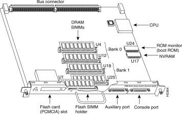
The Cisco IOS images reside in Flash memory, which is located either on the RSP7000, in the form of a single in-line memory module (SIMM), or on up to two Personal Computer Memory Card International Association (PCMCIA) cards (called Flash memory cards) that insert in the two PCMCIA slots (slot 0 and slot 1) on the front of the RSP7000. (See Figure 1-10.)
Storing the Cisco IOS images in Flash memory enables you to download and boot from upgraded Cisco IOS images remotely or from software images resident in the RSP7000 Flash memory, without having to remove and replace read-only memory (ROM) devices.
The RSP7000 contains the following components:
In addition to the system software, the RSP7000 contains and executes the following management functions that control the system:
The high-speed switching section of the RSP7000 communicates with and controls the interface processors on the high-speed CxBus. This switching section decides the destination of a packet and switches it accordingly. The RSP7000 uses a 16-million-instructions-per-second (mips) processor to provide high-speed, autonomous switching and routing.
Figure 1-10 shows the various types of memory components on the RSP7000, and Table 1-4 lists the functions of each type.
| Type | Size | Quantity | Description | Location |
DRAM | 16 to 128 MB | 2 to 4 | 8, 16, or 32-MB SIMMs (based on maximum DRAM required) | Bank 0: U4 and U12 |
NVRAM | 128 KB | 1 | Nonvolatile EPROM for the system configuration file1 | U17 |
Flash SIMM | 8 MB | 1 | Contains the Cisco IOS images on the RSP7000 (standard) | U1 |
Boot ROM | 256 KB | 1 | EPROM for the ROM monitor program | U24 |
| 1A system configuration file is contained in NVRAM, which allows the software to control several system variables. 2Only Intel Series 2 Flash memory cards can be used with the RSP7000. |
DRAM stores routing tables, protocols, and network accounting applications. The standard RSP7000 configuration is 16 megabytes (MB) of DRAM, with up to 128 MB available through single in-line memory module (SIMM) upgrades.
The system configuration, software configuration register settings, and environmental monitoring logs are contained in the 128-kilobyte (KB), nonvolatile random-access memory (NVRAM), which is backed up with built-in lithium batteries that retain the contents for a minimum of five years. When replacing an RSP7000, be sure to back up your configuration to a remote server so you can retrieve it later.
 | Caution Before you replace an RSP7000, back up the running configuration to a Trivial File Transfer Protocol (TFTP) file server so you can retrieve it later. If the configuration is not saved, the entire configuration will be lost—inside the NVRAM on the removed RSP7000—and you will have to reenter the entire configuration manually. For instructions on how to save the configuration file, refer to the section "Saving and Retrieving the Configuration File," in the chapter "Maintenance." This procedure is not necessary if you are temporarily removing an RSP7000 you will reinstall; lithium batteries retain the configuration in memory until you replace the RSP7000 in the system. |
The imbedded or PCMCIA card-based Flash memory allows you to remotely load and store multiple Cisco IOS and microcode images. You can download a new image over the network or from a local server and then add the new image to Flash or replace the existing files. You can then boot routers either manually or automatically from any of the stored images. Flash memory also functions as a TFTP server to allow other servers to boot remotely from stored images or to copy the stored image into their own Flash memory.
 | Caution The formatting procedure erases all information on the Flash memory card. To prevent the loss of important data that might be stored on a Flash memory card, proceed carefully. If you want to save the data on a Flash memory card, copy the data to a server before you format the card. |
The Cisco 7000 series routers support downloadable system software and microcode for most Cisco IOS and microcode upgrades, which enables you to remotely download, store, and boot from a new image. Flash memory contains the default system software. An erasable programmable read-only memory (EPROM) device contains the latest microcode version, in compressed form, for each interface processor. At system startup, an internal system utility scans for compatibility problems between the installed interface processor types and the bundled microcode images, then decompresses the images into running dynamic random-access memory (DRAM). The bundled microcode images then function the same as the EPROM images.
There are no user-configurable jumpers on the RSP7000.
The two LEDs on the RSP7000 indicate the system and RSP7000 status. The normal LED is on when the system is operational. During normal operation, the CPU halt LED should be off. The CPU halt LED goes on only if the system detects a processor hardware failure.
Two asynchronous serial ports on the RSP7000, the console and auxiliary ports, allow you to connect external devices to monitor and manage the system. The console port is an Electronic Industries Association/Telecommunications Industry Association (EIA/TIA)-232 receptacle (female) that provides a data circuit-terminating equipment (DCE) interface for connecting a console terminal.
The auxiliary port is an EIA/TIA-232 plug (male) that provides a data terminal equipment (DTE) interface; the auxiliary port supports flow control and is often used to connect a modem, a channel service unit (CSU), or other optional equipment for Telnet management.
The RSP7000CI, shown in Figure 1-11, works with the RSP7000, and consists of a printed circuit board attached to a metal carrier. The RSP7000CI has no user-configurable jumpers or switches, and its faceplate contains no LEDs. The RSP7000CI is distinguishable only by the label on its faceplate, which reads 7000 Series Chassis Interface. (See Figure 1-11.) The RSP7000CI provides the environmental monitoring and power supply monitoring functions for the Cisco 7000 series chassis. The RSP7000CI isolates the CPU and system software from chassis-specific variations.
 | Caution To prevent system problems, the RSP7000CI must not be removed or installed with power ON to the chassis. The RSP7000CI does not support online insertion and removal (OIR). You must install the RSP7000CI in the 7000 CI slot (slot 4 in the Cisco 7010). |
The functions of the RSP7000CI are as follows:

The SP, shown in Figure 1-12, controls and communicates with the interface processors on the high-speed CxBus. Its function is to decide the destination of a packet and switch it based on that decision. The SP uses a 16-million-instructions-per-second (mips) processor to provide high-speed, autonomous switching and routing. The SP microcode (firmware), which contains board-specific software instructions, resides in an ROM component in socket U173.
The SP is always installed in the SP slot, which is below the RP. (See Figure 1-3.) The single enabled LED is on when the SP is enabled for operation.

The SSP is the optional high-performance silicon switch for Cisco 7000 series routers. The SSP provides distributed processing and control for the interface processors, and communicates with and controls the interface processors on the high-speed CxBus. The SSP determines the destination of a packet and switches the packet, based on that decision.
The SSP is always installed in the backplane SP slot adjacent to the RP. A few seconds after bootup, the enabled LED comes on to indicate that the SSP is enabled for operation.
One SSP (or SP) is required in each Cisco 7000 series router.
There are two hardware versions of the SSP: one with 512 KB of packet memory and another with 2 MB of packet memory (for installations requiring increased memory capacity).
Following are minimum system requirements for the SSP types:
An interface processor comprises a modular, self-contained interface board and one or more network interface connectors in a single 11 x 14-inch unit. All CxBus interface processors support Online Insertion and Removal (OIR), so you can install and remove them without opening the chassis and without turning off the chassis power. (The early serial interface processor, known as the SX-SIP or PRE-FSIP, will not operate in the Cisco 7010; see the following Caution.) The RP, SP, and SSP, which are required system components, always reside in the RP, SP, and SSP slots. (See Figure 1-3.)
The remaining three slots are available for any combination of the following interface processors:
The microcode on the SP (and SSP) and on each interface processor contains board-specific software instructions. New features and enhancements to the system or interfaces are often implemented in microcode upgrades. The Cisco 7000 series routers support downloadable microcode for most maintenance upgrades, which enables you to download new microcode images remotely and store them in Flash memory. You can then use software commands to instruct the system to load a specific microcode image from Flash or to load the default microcode image from ROM.
System software upgrades also can contain upgraded microcode images, which will load automatically when the new software image is loaded. Although most upgrades support the downloadable microcode feature and are distributed on floppy disk, some may require ROM replacement. If replacement is necessary, refer to the section "Microcode Component Replacement" in the chapter "Maintenance." Also, specific instructions are provided with the replacement component in an upgrade kit.
Each interface processor has a unique bank of status LEDs, and all have a common enabled LED at the left end of the interface processor face plate. The enabled LED goes on when the RP has completed initialization of the interface processor for operation, indicating that, as a minimum, the interface processor is correctly connected to the backplane, that it is receiving power, and that it contains a valid microcode version. If any of these conditions is not met, or if the initialization fails for other reasons, the enabled LED stays off. Additional LEDs on each interface processor type indicate the state of the interfaces.
The following sections describe each interface processor type. The appendix "Reading LED Indicators" describes the specific LED states of each.
The AIP provides a direct connection between the high-speed CxBus and the external networks. (See Figure 1-13.) The physical layer interface module (PLIM) on the AIP determines the type of ATM connection.
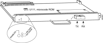
Table 1-5 lists the maximum number of AIP modules supported on Cisco 7000 series routers. There are no restrictions on slot locations or sequence; an AIP can be installed in any available interface processor slot.
| Chassis | Maximum AIP Modules |
|---|---|
Cisco 7000 (7-slot system) | 5 |
Cisco 7010 (5-slot system) | 3 |
The AIP supports the following features:
The CIP provides up to two channel attachment interfaces, eliminating the need for a separate front-end processor. (See Figure 1-14.) The CIP interfaces are combinations of a bus and tag (also called an original equipment manufacturer's interface [OEMI] and a parallel I/O interface) adapter and/or an Enterprise Systems Connection (ESCON) adapter.
The bus and tag adapter is called the Parallel Channel Adapter (PCA) and the ESCON adapter is called the ESCON Channel Adapter (ECA). The PCA and ECA connect directly to the CIP motherboard, and any combination of the two adapters can be used on the CIP.
While up to three CIPs can be installed in the Cisco 7010, we recommend that you leave one slot available for a WAN interface. The default CIP microcode boot image resides on an ROM in socket U37.
The supported processor input/output architectures for the CIP include ESA/390 for ESCON and System/370, 370/Xa, and ESA/390 for bus and tag. The ESCON interface is capable of a data rate up to 17 megabytes per second (MBps) and the bus and tag interface is capable of a data rate up to 4.5 MBps.
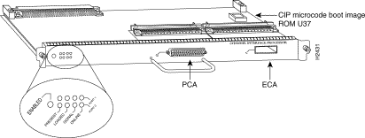
Following are the functions of the CIP LEDs.
The EIP, shown in Figure 1-15, provides two, four, or six Ethernet ports that operate at up to 10 Mbps. Each port supports both Ethernet Version 1 and IEEE 802.3/Ethernet Version 2 interfaces. A bit-slice processor provides a high-speed data path between the EIP and other interface processors. The default EIP microcode resides on a ROM in socket U101.
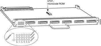
As with the other interface processors, the enabled LED is on when the EIP is enabled for operation. The three LEDs for each port indicate the following:
For complete descriptions of the LED states, refer to the appendix "Reading LED Indicators."
The EIP is available with two, four, or six ports. The Cisco 7010 supports up to three EIPs for a maximum of 18 Ethernet ports. Each port requires an Ethernet transceiver or a media attachment unit (MAU) and attachment unit interface (AUI) cable to connect to the external network. For descriptions of Ethernet transceivers and AUIs, refer to the section "Ethernet Connection Equipment" in the chapter "Preparing for Installation." For descriptions of Ethernet network connections, refer to the section "Ethernet Connections" in the chapter "Installing the Router."
Each port on the EIP automatically supports both Ethernet Version 1 and Version 2/IEEE 802.3 connections. When an interface is connected to an EIP port, the port automatically adjusts to the interface type. The ports are independent, so you can mix both versions on one EIP.
The FEIP provides up to two 100-Mbps, IEEE 802.3u 100BaseT ports. (Figure 1-16 shows a two-port FEIP.) IEEE 802.3u specifies several different physical layers for 100BaseT: 100BaseTX—100BaseT half duplex, over Category 5, unshielded twisted-pair (UTP), EIA/TIA-568-compliant cable; 100BaseFX—100BaseT full duplex, over twisted pair or optical fiber); and 100BaseT4—100BaseT full duplex, using Category 3 and 4 cabling with four pairs (also called 4T+).
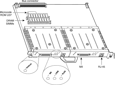
Following are the product numbers associated with the FEIP:
The interfaces on an FEIP can both be configured at 100 Mbps, half duplex (HDX) or full duplex (FDX), for a maximum aggregate bandwidth of 200 Mbps. The FEIP microcode boot image resides in an EPROM in socket location U37.
For maximum port densities, refer to the section "Port Densities" in this chapter.
The FIP contains a 16-mips processor for high-speed (100 Mbps) interface rates and the industry-standard AMD SuperNet chipset for interoperability. Figure 1-17 shows a multimode/multimode FIP on the bottom and a single-mode/multimode FIP on the top. The FIP supports single-attach stations (SASs), dual-attach stations (DASs), dual homing, and optical bypass. The FIP complies with ANSI X3.1 and ISO 9314 FDDI standards. The default FIP microcode resides on a ROM in socket U23.
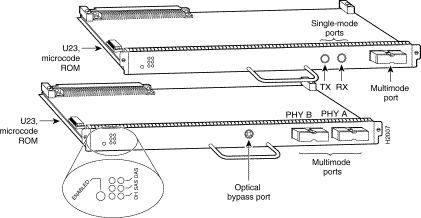
Each FIP provides a single network interface for both multimode and single-mode FDDI networks. The two FIP connectors are available in any combination of multimode (MIC) or single-mode (FC) connectors for matching multimode and single-mode fiber in the same FDDI network. The following combinations are available:
As with the other interface processors, the enabled LED is on when the FIP is enabled for operation. To the right of the enabled LED, a bank of six LEDs indicate the state of the two physical sublayer connections (PHY B and PHY A). The left column of three LEDs indicates PHY B; the right column indicates PHY A. (On the front of the FIP, the left interface is PHY B and the right interface is PHY A as shown in Figure 1-17.) The state of each B/A pair of LEDs indicates the status of one type of three possible station connections: dual-homed, single-attach station (SAS), or dual-attach station (DAS). For complete descriptions of the LED states, refer to the appendix "Reading LED Indicators."
Each FIP provides the interface for connection to a Class A DAS (with primary and secondary rings), or to a Class B SAS (with only a primary ring). The Cisco 7010 supports up to three FIPs for a maximum of 3 FDDI network connections. The multimode MIC or single-mode FC ports on the FIP provide a direct connection to the external FDDI network.
A six-pin mini-DIN connector on the multimode-multimode (CX-FIP-MM) and single-mode (CX-FIP-SS) FIPs provides the connection for an optical bypass switch. When the interface is shut down, the bypass switch allows the light signal to pass directly from the receive port to the transmit port on the bypass switch, completely bypassing the FIP transceivers. The bypass switch does not repeat the signal, and significant signal loss may occur when transmitting to stations at maximum distances. Optical bypass switches typically use a six-pin DIN or mini-DIN connector. A DIN-to-mini-DIN adapter cable (CAB-FMDD) is included with the FIP to allow connection to either type of connector. For a detailed description of optical bypass and FDDI connections, refer to the section "FDDI Connection Equipment" in the chapter "Preparing for Installation." For descriptions of FDDI network connections, refer to the section "FDDI Connections" in the chapter "Installing the Router."
The FSIP provides four or eight channel-independent, synchronous serial ports that support full duplex operation at T1 (1.544 Mbps) and E1 (2.048 Mbps) speeds. Each port supports any of the available interface types: EIA/TIA-232, EIA/TIA-449, V.35, X.21, EIA-530, and E1-G.703/G.704.
Figure 1-18 shows an eight-port FSIP. The eight ports are divided into two four-port modules, each of which is controlled by a dedicated Motorola MC68040 processor and contains 128 kilobytes (KB) of static random-access memory (SRAM). Each module can support up to four T1 or three E1 interfaces, and an aggregate bandwidth of up to 6.132 Mbps at full-duplex operation. The type of electrical interface, the amount of traffic, and the types of external data service units (DSUs) connected to the ports affect actual rates. For information on setting up high-speed interfaces, refer to the section "Replacing RSP7000 DRAM SIMMs" in the chapter "Maintenance."
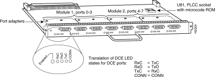
Each FSIP comprises an FSIP board with two or four port adapters installed. Additional port adapters are available as spares so that you can replace one that fails; however, you cannot upgrade a four-port FSIP to an eight-port by adding port adapters. The 4-port FSIP is not constructed to support additional ports after it leaves the factory; it contains the circuitry to control only one 4-port module. For port adapter descriptions, refer to the section "Universal Serial Port Adapters" in this chapter.
The default FSIP microcode resides on a PLCC-type ROM in socket U81.
The Cisco 7010 supports up to three FSIPs for a maximum of 24 high-speed serial interfaces. There are no restrictions on slot locations or sequence; you can install FSIPs in any available interface processor slots. For descriptions of serial connection equipment, refer to the section "Serial Connection Equipment" in the chapter "Preparing for Installation." For examples of network connections, refer to the section "Serial Connections" in the chapter "Installing the Router."
All interface types except EIA-530 are individually configurable for operation with either external timing (DTE mode) or internal timing (DCE mode); EIA-530 operates with external timing only. In addition, all interfaces support nonreturn to zero (NRZ) and nonreturn to zero inverted (NRZI) format, and both 16-bit and 32-bit cyclic redundancy checks (CRCs). The default configuration is for NRZ format and 16-bit CRC. You can change these default settings with software commands. (See the section "Replacing RSP7000 DRAM SIMMs" in the chapter "Maintenance.")
In order to provide a high density of ports, the FSIP uses special port adapters and adapter cables. A port adapter is a daughter card that provides the physical interface for two FSIP ports. Both ports use the same high-density, 60-pin universal receptacle that supports all interface types. The adapter cable connected to the port determines the interface type and mode.
The interface ports are not set to a default mode or for a default clock source, so there are no software commands required to enable internal or external timing (DCE or DTE). Each port automatically supports the mode of the port adapter cable when one is connected; however, there is no default clockrate set. You must set the clockrate on all DCE ports with the clockrate command before the port can operate with an external timing signal. To use the port as a DCE interface, you must set the clockrate and connect a DCE adapter cable.
To use the port as a DTE interface, you need only connect a DTE adapter cable to the port. If you connect a DTE cable to a port on which a clockrate is set, the system will ignore the clockrate until a DCE cable is attached. For example, you can change an interface from an EIA/TIA-232 to a V.35 by replacing the adapter cable, or change the mode of an EIA/TIA-232 DTE port by replacing the EIA/TIA-232 DTE cable with an EIA/TIA-232 DCE cable, provided that you have already specified a clockrate for the port.
Figure 1-18 shows the FSIP LEDs. As with the other interface processors, the enabled LED is on when the FSIP is enabled for operation. The four LEDs below each port indicate the state of that interface. The labels on each LED indicate the signal state when the FSIP port is in DTE mode. However, the direction of the signals is reversed when the FSIP port is in DCE mode. For example, a DCE device usually generates a clock signal, which it sends to the DTE device. Therefore, when the Receive Clock (RxC) LED on a DTE interface is on, it indicates that the DTE is receiving the clock signal from the DCE device. However, when the RxC LED on a DCE interface is on, it indicates that the DCE is sending a clock signal to the DTE device. Because of limited space on the FSIP faceplate, only DTE mode states are labeled on each port. Figure 1-18 shows the interpretation of each LED for ports that are operating in DCE mode.
The following LED state descriptions include the meanings for both DTE and DCE interfaces. The signals indicated for DTE interfaces correspond to the LED labels. However, the signals on DCE interfaces travel in the opposite direction and do not correspond directly to the LED labels. Refer to the LED labels for DTE interfaces and the cross-reference for DCE signals shown in Figure 1-18 when reviewing the LED state descriptions that follow:
For complete descriptions of the LED states, refer to the appendix "Reading LED Indicators."
The FSIP uses special universal serial port adapters and adapter cables to allow the high density (eight) of interface ports on an FSIP, regardless of the size or form factor of the connectors typically used with each electrical interface type. Figure 1-19 shows a universal port adapter with 60-pin connectors that support all interface types. The adapter cable connected to the port determines the interface type and mode.
The universal port adapters are field-replaceable daughter cards mounted to the FSIP, and each provides two high-density connectors for two FSIP ports. (See Figure 1-19.) The 60-pin D-shell receptacle supports EIA/TIA-232, V.35, EIA/TIA-449, X.21, and EIA-530.

The router (FSIP) end of all universal-type adapter cables is a 60-pin plug that connects to the 60-pin port (receptacle) on the FSIP. The network end of the cable is an industry-standard connector for the type of electrical interface that the cable supports: DB-25 for EIA/TIA-232 and EIA-530, DB-37 for EIA/TIA-449, DB-15 for X.21, or a standard V.35 block connector. For most interface types, the adapter cable for DTE mode uses a plug at the network end, and the cable for DCE mode uses a receptacle at the network end. However, V.35 adapter cables are available with either a V.35 plug or a receptacle for either mode, and EIA-530 is available only in DTE mode with a DB-25 plug. Factory-installed 4-40 thumbscrews are standard at the network end of all cable types except V.35. A metric conversion kit with M3 thumbscrews is included with each cable to allow connection to devices that use metric hardware.
The FSIP is shipped from the factory with two or four dual-port adapters installed. Additional port adapters are available as spares so that you can replace one that fails; however, you cannot upgrade a four-port FSIP to an eight-port by adding port adapters. (The four-port FSIP is manufactured with only one four-port module and processor.)
For port adapter replacement instructions, refer to the section "Replacing Serial Port Adapters" in the chapter "Maintenance." The appendix "Cabling Specifications" provides adapter cable pinouts; however, because the FSIP uses a special high-density port that requires special adapter cables for each electrical interface type, we recommend that you obtain serial interface cables from the factory.
The FSIP E1-G.703/G.704 interface connects Cisco 7000 series routers with 2.048-Mbps leased line services. The interface eliminates the need for a separate, external data termination unit to convert a standard serial interface (such as V.35) to a G.703/G.704/G.732 interface.
The FSIP can be configured to support up to eight E1-G.703/G.704 ports (four ports per module, two modules per FSIP). FSIP bandwidth can be allocated by the user, and the maximum aggregate bandwidth per four-port module is 16 Mbps, full duplex. We recommend that you leave one port on each module shut down to avoid exceeding this 16-Mbps maximum per module. Each of the four interfaces can operate up to 2.048 Mbps, which potentially presents a load greater than 16 Mbps, full duplex, if all four interfaces are configured. Eight E1-G.703/G.704 ports can be supported up to the 16-Mbps aggregate bandwidth capability; however, it is not possible to simultaneously support eight E1-G703/G.704 ports at 100-percent peak bandwidth utilization, without exceeding the 16-Mbps maximum per module.
Two versions of the E1-G.703/G.704 interface are available: one supports balanced mode, and the other supports unbalanced mode. Neither the modes nor the cables are interchangeable; you cannot configure a balanced port to support an unbalanced line, nor can you attach an interface cable intended for a balanced port to an unbalanced port.
The FSIP E1-G.703/G.704 interface supports both framed and unframed modes of operation, a loopback test, and a four-bit cyclic redundancy check (CRC). The interface can operate with either a line-recovered or an internal clock signal. The FSIP is configured at the factory with from one to four E1-G.703/G.704 port adapters. Each port adapter provides two 15-pin D-shell (DB-15) receptacles, which support only E1-G.703/G.704 interfaces.
The FSIP E1-G.703/G.704 interface uses a DB-15 receptacle for both the balanced and unbalanced ports. The label adjacent to the port indicates whether the port is balanced or unbalanced; you must connect the correct type of interface cable, or the port will not operate.
Figure 1-20 shows the 15-pin port and the label that indicates either balanced or unbalanced mode.

The FSIP end of all E1-G.703/G.704 adapter cables is a 15-pin D-shell connector (DB-15). At the network end, the adapter cable for unbalanced connections uses a BNC connector. The adapter cables for balanced mode are available with several connector types to accommodate connection standards in different countries. You must use the proprietary cables to connect the E1-G.703/G.704 port to your network.
Cables for balanced and unbalanced mode are available with the following types of network-end connectors:
In addition, some connections require bare-wire connections (directly to terminal posts).
Table 1-6 lists the model numbers and descriptions of the E1-G.703/G.704 port adapters and cables.
| Port Adapter and Cable Model Numbers | Description |
|---|---|
PA-7KF-E1/120=1 | Dual-port E1-G.703/G.704 120 ohm, balanced |
PA-7KF-E1/75= | Dual-port E1-G.703/G.704 75 ohm, unbalanced |
CAB-E1-TWINAX= | E1 cable twinax 120 ohm, balanced, 5 m |
CAB-E1-DB15= | E1 cable, DB-15, 120 ohm, balanced, 5 m |
CAB-E1-BNC= | E1 cable BNC 75 ohm, unbalanced, 5 m |
| 1The appended equal sign (=) indicates a spare part. |
The HIP, shown in Figure 1-21, provides a full-duplex synchronous serial interface for transmitting and receiving data at rates of up to 52 Mbps. The HSSI interface, recently standardized as EIA/TIA-612/613, provides access to services at T3 (45 Mbps), E3 (34 Mbps), and SONET STS-1 (51.82 Mbps) rates. The actual rate of the interface depends on the external data service unit (DSU) and the type of service to which it is connected. The default HIP microcode resides on an ROM in socket U133.
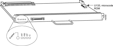
As with the other interface processors, the enabled LED is on when the HIP is enabled for operation. The four LEDs above the HSSI port (see Figure 1-21) indicate the following:
For complete descriptions of the LED states, refer to the appendix "Reading LED Indicators."
The HIP interface port is a 50-pin, SCSI-II-type receptacle. You need a HSSI interface cable to connect the HIP with an external DSU. Although the HSSI port and cable are physically similar to SCSI-II format, the HSSI specification is more stringent than that for SCSI-II, and we cannot guarantee reliable operation if a SCSI-II cable is used.
A null modem cable allows you to connect two collocated routers back to back to verify the operation of the HSSI interface or to build a larger node by linking the routers directly. For a description of HSSI network and null modem connections, refer to the section "HSSI Connections" in the chapter "Installing the Router." The appendix "Cabling Specifications" provides connector pinouts and cable assembly drawings.
The Cisco 7010 supports up to three HIPs for a total of three HSSI interfaces. There are no restrictions on slot locations or sequence; you can install a HIP in any available interface processor slot.
The MIP provides up to two channelized E1 or T1 connections via serial cables to a channel service unit (CSU). On the MIP, two controllers can each provide up to 24 virtual channels. Each virtual channel is presented to the system as a serial interface that can be configured individually.
The MIP, shown in Figure 1-22, provides two controllers for transmitting and receiving data bidirectionally at the T1 rate of 1.544 Mbps (in a future version at the E1 rate of 2.044 Mbps). For wide-area networking, the MIP can function as a concentrator for a remote site.

There are no restrictions on slot locations or sequence; you can install a MIP in any available interface processor slot. The MIP is compatible with any Cisco 7000 series router that is operating with the following software and microcode:
Refer to the appropriate software configuration and command reference publications for specific configuration information.
The TRIP, shown in Figure 1-23, provides two or four Token Ring ports for interconnection with IEEE 802.5 and IBM Token Ring media. The TRIP uses the IBM 16/4-Mbps chipset with an imbedded performance-enhanced interface driver and a 16.7-MHz bit-slice processor for high-speed processing. The speed on each port is independently software-configurable for either 4 or 16 Mbps. The default TRIP microcode resides on a ROM in socket U41.
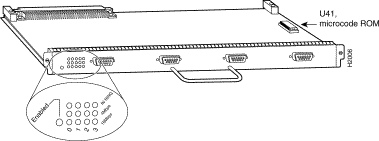
All TRIPs, regardless of whether they provide two or four ports, contain the bank of LEDs shown in Figure 1-23. As with the other interface processors, the enabled LED is on when the TRIP is enabled for operation. The three LEDs for each port indicate the following:
For complete descriptions of the LED states, refer to the appendix "Reading LED Indicators."
The TRIP is available with two or four ports. The Cisco 7010 supports up to 3 TRIPs for a maximum of 12 Token Ring ports. Each port requires a media access unit (MAU) to connect the DB-9 TRIP connectors to the external Token Ring networks.
For descriptions of Token Ring connectors and MAUs, refer to the section "Token Ring Connection Equipment" in the chapter "Preparing for Installation." For descriptions of Token Ring network connections, refer to the section "Token Ring Connections" in the chapter "Installing the Router."
This section describes functions that support the router's high availability and maintainability. Online insertion and removal (OIR) enables you to quickly install new interfaces without interrupting system power or shutting down existing interfaces. The environmental monitoring and reporting functions continuously monitor temperature and voltage points in the system, and provide reports and warning messages that enable you to quickly locate and resolve problems and maintain uninterrupted operation. These descriptions will help you become familiar with the capabilities of the router and the functional differences between the Cisco 7010 and other products.
The three available interface slots support any combination of network interface processors, or any three of the same type for the following maximum port densities:
You can install any combination of interface processors in any of the three available interface processor slots. There are no restrictions on either the number of interfaces possible or their location with respect to the main system processor (RP).
Each interface (port) in a Cisco 7000 series router uses several different types of addresses. The physical port address is the actual physical location (slot/port) of the interface connector within the chassis. The system software uses the physical addresses to control activity within the router and to display status information. These physical slot/port addresses are not used by other devices in the network; they are specific to the individual router and its internal components and software.
The system software also assigns a logical interface address to each interface, which is included in some of the status displays. The logical address is used in our other modular platforms (A-type, M, and C chassis) and is present in all router software, but it is not implemented (or needed) in the Cisco 7000 series routers.
The following sections describe how Cisco 7000 series routers assign and control both the physical (slot/port) and MAC-layer addresses for interfaces within the chassis.
In the Cisco 7010, physical port addresses specify the actual physical location of each interface port on the router interface processor end. (See Figure 1-24.) The address is composed of a two-part number in the format slot/port number. The first number identifies the slot in which the interface processor is installed (0 through 2, beginning at the bottom slot). The second number identifies the physical port number on the interface processor. The ports on each interface processor are numbered sequentially from left to right beginning with the port 0.
Interface ports maintain the same address regardless of whether other interface processors are installed or removed. However, when you move an interface processor to a different slot, the first number in the address changes to reflect the new slot number. For example, on a six-port EIP in slot 1, the address of the first port (on the left) is 1/0 and that of the right-most port is 1/5. If you remove the EIP from slot 1 and install it in slot 2, the addresses of those same ports become 2/0 and 2/5.
Figure 1-24 shows some of the port numbers of a sample system.
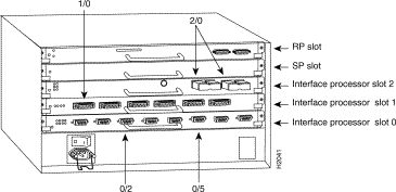
Interface slots are numbered 0 to 2 from the bottom slot up. The port numbers always begin at 0 and are numbered from left to right. The number of additional ports (/1, /2, and so on) depends on the number of ports available on an interface. FDDI interfaces are always n/0, because each FIP supports one interface. (The multiple connectors on the FIP can be misleading, but they provide multiple attachment options for a single FDDI interface.) Ethernet interfaces can be numbered from /0 through /5 because EIPs support up to six Ethernet ports. Serial interfaces on an eight-port FSIP are numbered /0 through /7, and so on.
You can identify interface ports by physically checking the slot/port location on the back of the router or by using software commands to display information about a specific interface or all interfaces in the router. To display information about every interface, use the show interfaces command (interfaces is plural) without variables. To display information about a specific interface, use the show interface command (interface is singular) with the interface type and port address in the format show interface [type slot/port]. If you abbreviate the command (sho int) and do not include variables, the system interprets the command as show interfaces and displays the status of all interfaces.
In the following example, most of the status information for each interface is omitted.
7010# show int


Serial0/0 is up, line protocol is up
  Hardware is cxBus Serial
  Internet address is 131.108.123.4, subnet mask is 255.255.255.0
  	(display text omitted)
Ethernet1/2 is up, line protocol is up
  Hardware is cxBus Ethernet, address is 0000.0c02.d0f1 (bia 0000.0c02.d0f1)
  	(display text omitted)


Fddi2/0 is administratively down, line protocol is down
  Hardware is cxBus Fddi, address is 0000.0c02.adc2 (bia 0000.0c02.adc2)
  Internet address is 131.108.31.4, subnet mask is 255.255.255.0
  (display text omitted)
You can also use variables such as the interface type (Ethernet, Token Ring, FDDI, serial, or HSSI) and the port address (slot/port) to display information about a specific interface only. The following example shows the display for the top Ethernet port on an EIP in slot 1:
7010# show int ether 4/0


Ethernet1/0 is up, line protocol is up
  Hardware is cxBus Ethernet, address is 0000.0c02.d0ce (bia 0000.0c02.d0ce)
  Internet address is 131.108.31.7, subnet mask is 255.255.255.0
  MTU 1500 bytes, BW 10000 Kbit, DLY 1000 usec, rely 255/255, load 1/255
  Encapsulation ARPA, loopback not set, keepalive set (10 sec)
  	(display text omitted)
For complete command descriptions and instructions, refer to the related software documentation, which is available on UniverCD.
All network interface connections (ports) require a unique Media Access Control (MAC)-layer address, which is also known as a physical or hardware address. Typically, the MAC address of an interface is stored on a component that resides directly on the interface circuitry, as it does on our earlier router platforms (for example, on individual appliques). Every interface on the earlier platforms contains a programmable read-only memory (PROM) component with a unique MAC address for that interface. The router system code reads the PROM for each interface in the system, learns the MAC addresses, and then initializes appropriate hardware and data structures.
However, the OIR feature makes it necessary to use a different method of handling the MAC addresses in Cisco 7000 series routers. OIR allows you to remove an interface processor and replace it with another identically-configured one. If the new interfaces match the current configuration (that of the interfaces you removed), the system immediately brings them on line. In order to allow OIR, an address allocator with 40 unique MAC addresses is stored in an EEPROM on the RP. (Because the RP is used on both the 7-slot and 5-slot platforms, the address bank must contain addresses for the maximum possible configuration: 40 possible interfaces [5 interface processor slots x 8 ports] in the 7-slot model. The 5-slot model uses only the first 24 addresses [3 interface processor slots x 8 ports] in the MAC allocator.) Each address is reserved for a specific slot/port in the router regardless of whether an interface resides in that port.
The MAC addresses are assigned to the ports in sequence; the first address is assigned to port 0/0, the ninth to port 1/0, and the last (40th) to port 4/8. This address scheme allows you to remove interface processors and insert them into other routers without causing the MAC addresses to move around the network or be assigned to multiple devices.
Note that if the MAC addresses were stored on each interface processor, OIR would not function because you could never replace one interface with an identically configured one; the MAC addresses would always be different. Also, each time an interface was replaced, other devices on the network would have to update their data structures with the new address and, if they did not do so quickly enough, could cause the same MAC address to appear in more than one device at the same time. Storing the MAC addresses on the RP avoids these problems. When an interface is replaced with another interface with the same configuration, there is no need for other devices in the network to update their data structures and routing tables.
Storing the MAC addresses for every port in one central location on the RP also means that the MAC addresses stay with the RP on which they are stored. If you replace the RP, the addresses of all ports will change to those specified in the address allocator on the new RP. Because the system configuration is also stored on the RP (in NVRAM) and stays with the RP when you remove it, you will need to reenter the configuration if you replace the RP.
Before replacing an RP, you must back up the running configuration to a TFTP file server so that you can later retrieve it. If the configuration is not saved, the entire configuration will be lost—inside the NVRAM on the removed route processor—and you will have to reenter it manually. This procedure is not necessary if you are temporarily removing an RP you will reinstall; lithium batteries retain the configuration in memory until you replace the RP in the system.
The OIR function allows you to install and replace interface processors while the system is operating; you do not need to notify the software or shut down the system power. All CxBus interface processors (AIP, CIP, EIP, FIP, FSIP, HIP, MIP, and TRIP) support OIR. The following is a functional description of OIR for background information only; for specific procedures for installing and replacing interface processors on line, refer to the section "Online Insertion and Removal Information" in the chapter "Maintenance."
All CxBus interface processors support OIR; however, you must shut down the system before removing or installing the RP or SP (or SSP), both of which are required system components. Removing an RP or SP (or SSP) while the system is operating will cause the system to shut down or crash, and might damage or destroy memory files.
Each RP, SP (or SSP), and interface processor contains a bus connector with which it connects to the system backplane. The bus connector is a set of tiered pins, in three lengths. The pins send specific signals to the system as they make contact with the backplane. The system assesses the signals it receives and the order in which it receives them to determine what event is occurring and what task it needs to perform, such as reinitializing new interfaces or shutting down removed ones.
For example, when you insert an interface processor, the longest pins make contact with the backplane first, and the shortest pins make contact last. The system recognizes the signals and the sequence in which it receives them. The system expects to receive signals from the individual pins in this logical sequence, and the ejector levers help to ensure that the pins mate in this sequence.
When you remove or insert an interface processor, the backplane pins send signals to notify the system, which then performs as follows:
1. Rapidly scans the backplane for configuration changes and does not reset any interfaces.
2. Initializes all newly inserted interface processors, noting any removed interfaces and placing them in the administratively shutdown state.
3. Brings all previously configured interfaces on the interface processor back to the state they were in when they were removed. Any newly inserted interfaces are put in the administratively shutdown state, as if they were present (but unconfigured) at boot time. If a similar interface processor type has been reinserted into a slot, then its ports are configured and brought on line up to the port count of the original interface processor.
OIR functionality enables you to add, remove, or replace interface processors with the system online, which provides a method that is seamless to end users on the network, maintains all routing information, and ensures session preservation.
When you insert a new interface processor, the system runs a diagnostic test on the new interfaces and compares them to the existing configuration.
If this initial diagnostic test fails, the system remains off line for another 15 seconds while it performs a second set of diagnostic tests to determine whether or not the interface processor is faulty and if normal system operation is possible.
If the second diagnostic test passes, which indicates that the system is operating normally and the new interface processor is faulty, the system resumes normal operation but leaves the new interfaces disabled. If the second diagnostic test fails, the system crashes, which usually indicates that the new interface processor has created a problem in the bus and should be removed.
The system brings on line only interfaces that match the current configuration and were previously configured as up; all other interfaces require that you configure them with the configure command. On interface processors with multiple interfaces, only the interfaces that have already been configured are brought on line.
The Cisco 7000 series routers support downloadable microcode for most upgrades, which enables you to load new microcode images into Flash memory instead of replacing the microcode ROMs on the boards.The latest microcode version for each interface processor type is bundled with the system software image. New microcode images are now distributed on floppy disk as part of a software maintenance release; microcode upgrades are no longer distributed individually.
The default operation is to load the microcode from the bundled image. At system startup, an internal system utility scans for compatibility problems between the installed interface processor types and the bundled microcode images, then decompresses the images into running memory (RAM). The bundled microcode images then function the same as images loaded from the individual microcode ROMs on the processor modules. You can override the default and instruct the system to load a specific microcode image from a Flash memory file or from the microcode ROM with the microcode [card type] flash [file name] command.
The show microcode command lists all of the microcode images that are bundled with the system software image. In order to support OIR, the system loads a microcode image for all available processor types.
Following is an example of the show microcode command:
Router# show microcode

Microcode bundled in system

Card    Microcode    Target Hardware    Description
Type    Version      Version
----    ---------    ---------------    -----------
EIP      10.1              1.x          EIP version 10.1
FIP      10.2              2.x          FIP version 10.2
TRIP     10.1              1.x          TRIP version 10.1
AIP      10.5              1.x          AIP version 10.5
FEIP     10.1              1.x          FEIP version 10.1
FSIP     10.6              1.x          FSIP version 10.6
HIP      10.2              1.x          HIP version 10.2
MIP      11.0              1.x          MIP version 11.0
CIP      10.3              1.x          CIP version 10.3

Router#
The microcode version and description lists the bundled microcode version for each processor type, which is not necessarily the version that is currently loaded and running in the system. A microcode image that is loaded from ROM or a Flash memory file is not shown in this display. To display the currently loaded and running microcode version for each processor type, issue the show controller cxbus command.
The target hardware version lists the minimum hardware revision required to ensure compatibility with the new software and microcode images. When you load and boot from a new bundled image, the system checks the hardware version of each processor module that it finds installed and compares the actual version to its target list. If the target hardware version is different from the actual hardware version, a warning message appears when you boot the router, indicating that there is a disparity between the target hardware and the actual hardware. You will still be able to load the new image; however, contact a service representative for information about upgrades and future compatibility requirements.
To display the current microcode version for each interface processor, enter the show controller cxbus command. The following example shows that the SP is running Microcode Version 1.4, and the FSIP is running Microcode Version 1.0:
7010# show cont cxbus


Switch Processor 5, hardware version 1.1, microcode version 1.4
  (display text omitted)
 FSIP 0, hardware version 4, microcode version 1.0
  (display text omitted)
Although most microcode upgrades are distributed on floppy disk, some exceptions may require ROM replacement. If so, refer to the chapter "Maintenance" for replacement procedures. Instructions are also provided with the upgrade kit. For complete command descriptions and instructions, refer to the related software documentation.
The environmental monitoring and reporting functions enable you to maintain normal system operation by identifying and resolving adverse conditions prior to loss of operation. Environmental monitoring functions constantly monitor the internal chassis air temperature and DC line voltages. The power supply monitors its own voltage and temperature and shuts itself down if it detects a critical condition within the power supply. If conditions reach shutdown thresholds, the system shuts down to avoid equipment damage from excessive heat or current. The reporting functions periodically log the values of measured parameters so that you can retrieve them for analysis later, and the reporting functions display warnings on the console if any of the monitored parameters exceed defined thresholds.
 | TimeSaver With Maintenance Release 9.17(10) and later, the system can identify which type of power supplies are in your chassis: DC-input or AC-input. As a general precaution, use the show environment all command and note the type of power supply indicated in each of your chassis (indicated as either "600W DC" or "550W AC"). Record and save this information in a secure place. |
The environmental monitoring functions use the following levels of status conditions to monitor the system. The processor uses the first four levels to monitor the temperature inside the processor slots, and the power supply uses the Normal and Critical levels to monitor DC voltages. Table 1-7 lists temperature thresholds for the first four (processor-monitored) levels. Table 1-8 lists the DC power thresholds for the Normal and Critical (power-supply-monitored) levels.
| Parameter | Warning | Normal | Warning | Critical | Shutdown |
|---|---|---|---|---|---|
Inlet air | < 10° C | 10-39° C | 39-46° C | 46-64° C | > 64° C |
Airflow1 | < 10° C | 10-70° C | 70-77° C | 77-88° C | > 88° C |
| 1These thresholds were corrected in Software Releases 9.17(8) and 9.21(3); refer to the description of the show environment table command in the next section, "Environmental Reports." |
| Parameter | Critical | Normal | Critical |
|---|---|---|---|
+5V | < 4.74V | 4.74-5.26V | > 5.26V |
+12V | < 10.20V | 10.20-13.8V | > 13.80V |
-12V | > -10.20V | -10.20- -13.80V | < -13.80V |
+24V | < 20.00V | 20.00-28.00V | > 28.00V |
The system processor uses the first four status levels (Normal, Warning, Critical, and Processor Shutdown) to monitor the air temperature in the interface processor compartment and the voltage levels on the four DC lines. Sensors on the RP monitor the temperature of the cooling air that flows through the processor slots.
If the air temperature exceeds a defined threshold, the system processor displays warning messages on the console terminal and, if the temperature exceeds the shutdown threshold, it shuts down the system. The system stores the present parameter measurements for both temperature and DC voltage in NVRAM, so that you can retrieve it later as a report of the last shutdown parameters.
The power supply self-monitors its own internal temperature and voltages. The power supply is either within tolerance (Normal) or out of tolerance (Critical level), as shown in Table 1-8. If an internal power supply temperature or voltage reaches a critical level, the power supply shuts down without any interaction with the system processor.
If the system detects that AC input power is dropping but it is able to recover before the power supply shuts down, it logs the event as an intermittent powerfail. The reporting functions display the cumulative number of intermittent powerfails logged since the last power up.
The system displays warning messages on the console if processor-monitored parameters exceed a desired threshold or if a fan failure occurs. You can also retrieve and display environmental status reports with the show environment, show environment all, show environment last and show environment table commands. Parameters are measured and reporting functions are updated every 60 seconds. A brief description of each of these commands follows. For complete command descriptions and instructions, refer to the related software documentation.
 | Caution Ensure that your system is drawing cool inlet air. Overtemperature conditions can occur if the system is drawing in the exhaust air of other equipment. When viewing the chassis from the interface processor end, the airflow inlet vents are on the right side of the chassis, and the exhaust vents are on the left. (See Figure 1-6.) Ensure adequate clearance around the sides of the chassis so that cooling air can flow through the chassis interior unimpeded. Obstructing or blocking the chassis sides will restrict the airflow and can cause the internal chassis temperature to exceed acceptable limits. |
The show environment command display reports the current environmental status of the system. The report displays the date and time of the query, the refresh times, the overall system status, and any parameters that are out of the normal values. No parameters are displayed if the system status is normal. The example that follows shows the display for a system in which all monitored parameters are within Normal range.
7010# show env


Environmental Statistics
  Environmental status as of Sat 10-31-1992 16:42:48
  Data is 0 second(s) old, refresh in 60 second(s)

  All Environmental Measurements are within specifications
If the environmental status is not normal, the system reports the worst-case status level in the last line of the display, instead of the status summary that is shown in the last line of the preceding example. For example, if the fan array is not operating properly, the system displays the following warning message:
WARNING: Fan has reached CRITICAL level
7010# show env last


Environmental Statistics
  Environmental status as of Sat 10-31-1992 16:42:48
  Data is 10 second(s) old, refresh in 50 second(s)

  All Environmental Measurements are within specifications

LAST Environmental Statistics
  Environmental status as of Thu 10-15-1992 12:22:43
  Power Supply: 550W, OFF

  No Intermittent Powerfails

  +12 volts measured at  12.05(V)
   +5 volts measured at   4.82(V)
  -12 volts measured at -12.00(V)
  +24 volts measured at  23.90(V)

  Air-Flow temperature measured at 32(C)
  Inlet    temperature measured at 26(C)
The show environment table command displays the temperature and voltage thresholds for each monitored status level, which are the same as those listed in Tables 1-7 and 1-8. The current measured values are displayed with the unit of measure noted, (V) or (C), and each is listed below a column heading that indicates its current status level. Measurements that fall within the Normal range are displayed in the Normal column of the table, while measurements that have reached a critical level are shifted to the Critical column, and so on.
%ENVM-2-TEMP: Airflow temperature has reached WARNING level at 60(C)
Temperature Parameters:

     SENSE     WARNING       NORMAL       WARNING       CRITICAL       SHUTDOWN
     -------|-------------|------------|-------------|--------------|--------------
     Inlet               10   24(C)   39            46             64
     Airflow             10           60    65(C)   70             88
7010# show env table


Environmental Statistics
  Environmental status as of Fri 11-5-1993 18:50:21
  Data is 46 second(s) old, refresh in 14 second(s)

  WARNING: Fan has reached CRITICAL level

Voltage Parameters:

 SENSE        CRITICAL                NORMAL                CRITICAL
-------|--------------------|------------------------|--------------------

+12(V)                    10.20      12.05(V)      13.80
 +5(V)                     4.74       4.96(V)       5.76
-12(V)                   -10.20     -12.05(V)     -13.80
+24(V)                    20.00      23.80(V)      28.00

Temperature Parameters:

SENSE     WARNING       NORMAL       WARNING       CRITICAL      SHUTDOWN
------|-------------|------------|-------------|--------------|------------

Inlet               10   32(C)   39            46             64
Air-flow            10   40(C)   70            77             88
The following example shows only the Temperature Parameters section of the table. In this example, the measured value at the inlet sensor is 41° C, which falls within the warning range (39° C through 46° C) and therefore is displayed in the Warning column.
Temperature Parameters:

SENSE     WARNING       NORMAL       WARNING       CRITICAL      SHUTDOWN
------|-------------|------------|-------------|--------------|------------

Inlet               10           39    41(C)   46             64
Air-flow            10   40(C)   70            77             88
The show environment all command displays an extended report that includes all the information in the show environment command display, plus the power supply status, the number of intermittent powerfails (if any) since the system was last powered on, and the measured values at the temperature sensors and the DC lines. The refresh time indicates that the parameters will be measured again in 29 seconds; any changes to a measurement will not be reflected in the display until at least 40 seconds have elapsed and the current information is refreshed.
7010# show env all


Environmental Statistics
  Environmental status as of Fri 11-5-1993 19:10:41
  Data is 31 second(s) old, refresh in 29 second(s)

  WARNING: Fan has reached CRITICAL level

  Power Supply: 550W AC

  No Intermittent Powerfails

  +12 volts measured at  12.00(V)
   +5 volts measured at   5.02(V)
  -12 volts measured at -12.05(V)
  +24 volts measured at  23.70(V)

  Airflow temperature measured at 35(C)
  Inlet   temperature measured at 26(C)
When the system power is on, all six fans in the fan array must be operational. If the system detects a failed or failing fan, it will display a warning message on the console screen. If the condition is not corrected within two minutes, the entire system will shut down to avoid an overtemperature condition and shutdown. The system uses a Hall Effect signal to monitor the six fans in the array. The current to the fans and the magnetic field generated by the fans' rotation generates a voltage, which the system monitors to determine whether or not all of the fans are operating. If the monitored voltage signal drops below a specified value, the system assumes a fan failure and initiates a fan shutdown.
In the following example, the system has detected an out-of-tolerance fan, which it interprets as a fan failure. The failure message is displayed for two minutes before the system shuts down.
%ENVM-2-FAN: Fan array has failed, shutdown in 2 minutes
If the system does shut down because of a fan failure, the system will display the following message on the console screen and in the show environment display when the system restarts:
Queued messages:
%ENVM-1-SHUTDOWN: Environmental Monitor initiated shutdown
For complete command descriptions and instructions, refer to the related software configuration and command reference documentation.
![]()
![]()
![]()
![]()
![]()
![]()
![]()
![]()
Posted: Wed Oct 31 17:57:55 PST 2001
All contents are Copyright © 1992--2001 Cisco Systems, Inc. All rights reserved.
Important Notices and Privacy Statement.