The Cisco 7010 router is part of the Cisco 7000 series. The five-slot Cisco 7010 router supports multiprotocol, multimedia routing and bridging with a wide variety of protocols and combinations of Asynchronous Transfer Mode (ATM), Ethernet, Fast Ethernet, Token Ring, Fiber Distributed Data Interface (FDDI), serial, High-Speed Serial Interface (HSSI), channel attachment, and multichannel media.
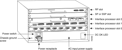
The Cisco 7010 has five slots: three interface processor slots (0 through 2), one slot for the Switch Processor (SP) or Silicon Switch Processor (SSP), and one slot for the Route Processor (RP). Two power supplies are available for the Cisco 7010: DC input or AC input. Network interfaces reside on interface processors, which provide a direct connection between the Cisco Extended Bus (CxBus) and external networks.
Note Your
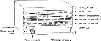
Cisco 7010 can also be optionally configured with a 7000 Series Route Switch Processor (RSP7000), which combines the routing and switching functions of the separate RP and SP. This new processor module requires that your Cisco 7010 also be configured with the 7000 Series Chassis Interface (RSP7000CI), which provides the environmental monitoring functions for the Cisco 7010. With this Cisco 7010 configuration, slot 3 (the 7000 RSP slot) is reserved for the RSP7000, and slot 4 (the 7000 CI slot) is reserved for the RSP7000CI. The remaining three slots (0 through 2) are reserved for interface processors. If your chassis was ordered with the RSP7000 option, both RSP7000-related components are installed when the Cisco 7010 ships.
Following is a list of acronyms that identify the system components and features:
Figure 1-1shows a view of the interface-processor end of the Cisco 7010 with an AC-input power supply, RP, and SP (or SSP) installed.
Figure 1-1: Cisco 7010 with RSP and SP (or SSP), Rear View

Figure 1-2 shows a view of the interface-processor end (rear) of the Cisco 7000 with an AC-input power supply, RSP7000, and RSP7000CI installed.
Figure 1-2: Cisco 7010 with RSP7000 and RSP7000CI, Rear View

Following are the specifications for the Cisco 7010 system.
Table 1-1: Cisco 7010 Specifications
| Description
| Specification
|
|---|
| High-speed backplane
| 533-Mbps CxBus, 3 interface processor slots, 1 RP slot, and 1 SP (or SSP) slot
|
| Dimensions (H x W x D)
| 10.5 x 17.5 x 17.0'' (26.67 x 44.45 x 43.18 cm)
Chassis depth including power cord and cable management brackets is 19'' (48.26 cm)
|
| Weight
| Chassis only (including power supply and fan array): 46 lb (20.87 kg)
Chassis fully configured with 1 RP, 1 SP (or 1 SSP), and 3 interface processors: 70 lb (31.75 kg)
|
| Power supply
| 600 watts (W) maximum
|
| Power dissipation
| 550W maximum configuration, 540W typical with maximum configuration
|
| Heat dissipation
| 715W (2440 British thermal units [Btus]/hr) with AC-input
300W (1024 Btus/hr) with DC-input
|
| Input voltage
| 100 to 240 VAC, wide input with power factor corrector (PFC)
|
| Power distribution
| 70A maximum @ +5VDC, 15A maximum @ +12VDC,
3A maximum @ -12VDC, 5A maximum @ +24VDC
|
| Frequency
| 50 to 60 Hz
|
| AC-input rating
| 9A maximum at 100 VAC, 4A maximum at 240 VAC at 600W
|
| DC-input rating
| -40 volts DC (VDC) minimum in North America (-56V in Europe)
-48 VDC nominal in North America (-60V in Europe)
-52 VDC maximum in North America (-75V in Europe)
|
| Airflow
| Side-to-side through the chassis using a variable-speed, 6-fan array
|
| Operating temperatures
| 32 to 104°F (0 to 40°C) and -4 to 149°F (-20 to 65°C) for nonoperating temperature
|
| Humidity
| 10 to 90%, noncondensing
|
| Agency approvals
| Safety: UL 1950, CSA 22.2-950, EN60950, EN41003, AUSTEL TS001, AS/NZS 3260
EMI: FCC Class A, EN60555-2, EN55022 Class B, VDE 0878 Part 3, 30 Class B
Immunity: EN55101/2 (ESD), EN55101/3 (RFI), EN55101/4 (Burst), EN55101/5 (Surge), EN55101/6 (Conducted), IEC77B (AC Disturbance)
|
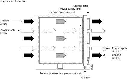
Six individual fans draw cooling air through the Cisco 7010 interior to maintain an acceptable operating temperature for the internal components. The fans draw air in through the inlet vents on the side of the chassis opposite the fans, across the processor modules and other internal components, and out through the exhaust vents adjacent to the fans, as shown in Figure 1-3.
Figure 1-3: Cisco 7010 Chassis Airflow

The sides of the chassis must remain unobstructed to ensure adequate airflow and prevent overheating inside the chassis. A temperature sensor on the RP monitors the internal air temperature. The power supply has two fans for cooling.
For complete information on fan operation and environmental considerations related to fan speed, refer to the Cisco 7010 Hardware Installation and Maintenance publication, which is available on UniverCD or as a printed copy. See the section "If You Need More Configuration Information," in the chapter "Performing a Basic Configuration of the Cisco 7010," for information on ordering UniverCD.


