|
|

This chapter describes our support for Systems Network Architecture (SNA) downstream physical unit (DSPU) devices and SNA Service Point. For a complete description of the commands mentioned in this chapter, refer to the "DSPU Configuration Commands" chapter of the Router Products Command Reference publication.
DSPU is a software feature that enables the router to function as a physical unit (PU) concentrator for SNA PU type 2 nodes. PU concentration at the router simplifies the task of PU definition at the upstream host while providing additional flexibility and mobility for downstream PU devices.
The DSPU feature allows you to define downstream PU type 2 devices in the router. DSPU reduces the complexity of host configuration by letting you replace multiple PU definitions that represent each downstream device with one PU definition that represents the router.
Because you define the downstream PUs at the router rather than the host, you isolate the host from changes in the downstream network topology. Therefore you can insert and remove downstream PUs from the network without making any changes on the host.
The concentration of downstream PUs at the router also reduces network traffic on the wide-area network (WAN) by limiting the number of sessions that must be established and maintained with the host. The termination of downstream sessions at the router ensures that idle session traffic does not appear on the WAN.
Our SNA Service Point support in the Cisco Router assumes NetView or an equivalent product at the SNA host. The user interacts with the network management feature in both the Router and at the SNA host. At the router you can configure the host connection, and show the status of this connection. At the SNA host you can use the Netview operator's console to view Alerts, and to send and receive Cisco syntax commands to the router.
Figure 30-1 shows a router functioning as a DSPU concentrator.
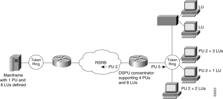
Typically, the router establishes one or more upstream connections with one or more hosts and many downstream connections with PU type 2 devices. From an SNA perspective, the router appears as a PU type 2 device to the upstream host and assumes the role of a system services control point (SSCP) appearing as a PU type 5 device to its downstream PUs.
The SSCP sessions established between the router and its upstream host are completely independent of the SSCP sessions established between the router and its downstream PUs. SNA traffic is routed at a logical unit (LU) level using a routing algorithm that maps downstream LUs onto upstream LUs.
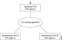
Figure 30-2 illustrates the SNA perspective of DSPU.
To configure DSPU, perform the tasks in the following sections. The last two tasks are optional.
See the end of this chapter for "DSPU Configuration Examples."
The upstream host provides LUs that the router will assign for use by its downstream PUs. Because one upstream host can only provide a maximum of 255 LUs, the DSPU feature supports multiple hosts. Multiple upstream host support allows the DSPU router to provide more than 255 LUs for use by its downstream PUs.
To define a DSPU host over TokenRing, Ethernet, or RSRB connections, perform the following task in global configuration mode:
| Task | Command |
|---|---|
Define a DSPU host over TokenRing/Ethernet or RSRB connections. | dspu host host-name xid-snd xid rmac remote-mac [rsap remote-sap] [lsap local-sap] [interface slot/port] [window window-size] [maxiframe max-iframe] [retries retry-count] [retry-timeout retry-timeout] [focalpoint] |
To define a DSPU host over an SDLC connection, perform the following task in global configuration mode:
| Task | Command |
|---|---|
Define a DSPU host over an SDLC connection | dspu host host-name xid-snd xid sdlc sdlc-addr [interface slot/port] [window window-size] [maxiframe max-iframe] [retries retry-count] [retry-timeout retry-timeout] [focalpoint] |
To define a DSPU host over an X.25/QLLC connection, perform the following task in global configuration mode:
| Task | Command |
|---|---|
Define a DSPU host over an X.25/QLLC connection. | dspu host host-name xid-snd xid x25 remote-x121-addr [qllc local-x121-sub-addr] [interface slot/port] [window window-size] [maxiframe max-iframe] [retries retry-count] [retry-timeout retry-timeout] [focalpoint] |
To define a DSPU host over a Frame Relay connection, perform the following task in global configuration mode:
| Task | Command |
|---|---|
Define a DSPU host over a Frame Relay connection. | dspu host host-name xid-snd xid dlci dlci-number [rsap remote-sap] [lsap local-sap] [interface slot/port] [window window-size] [maxiframe max-iframe] [retries retry-count] [retry-timeout retry-timeout] [focalpoint] |
To define the downstream PUs, perform either of the tasks in the following sections, depending on your circumstances:
Explicitly define a downstream PU if you require the router to perform verification checking on incoming downstream connections or to initiate an outgoing downstream connection.
To explicitly define a downstream PU over TokenRing, Ethernet, or RSRB connections, perform the following task in global configuration mode:
| Task | Command |
|---|---|
Explicitly define a downstream PU over TokenRing, Ethernet, or RSRB connections. | dspu pu pu-name rmac remote-mac [rsap remote-sap] [lsap local-sap] [xid-rcv xid] [interface slot/port] [window window-size] [maxiframe max-iframe] [retries retry-count] [retry-timeout retry-timeout] |
To define a DSPU host over an SDLC connection, perform the following task in global configuration mode:
| Task | Command |
|---|---|
Explicitly define a downstream PU over an SDLC connection. | dspu pu pu-name xid-rcv xid [sdlc sdlc-addr] [interface slot/port] [window window-size] [maxiframe max-iframe] [retries retry-count] [retry-timeout retry-timeout] |
To define a DSPU host over an X.25/QLLC connection, perform the following task in global configuration mode:
| Task | Command |
|---|---|
Explicitly define a downstream PU over an X.25/QLLC connection. | dspu pu pu-name [x25 remote-x121-addr] [qllc local-x121-sub-addr] [xid-rcv xid] [interface slot/port] [window window-size] [maxiframe max-iframe] [retries retry-count] [retry-timeout retry-timeout] |
To define a DSPU host over a Frame Relay connection, perform the following task in global configuration mode:
| Task | Command |
|---|---|
Explicitly define a downstream PU over a Frame Relay connection. | dspu pu pu-name [dlci dlci-number] [rsap remote-sap] [lsap local-sap] [xid-rcv xid] [interface slot/port] [window window-size] [maxiframe max-iframe] [retries retry-count] [retry-timeout retry-timeout] |
Note that a PU definition must have either an xid-rcv parameter or an address (rmac, sdlc, x25 or dlci) parameter.
If the router will perform verification checking on incoming downstream connections, there are several combinations of parameters that you can configure for verification matching. Note that the address parameter, when specified, is considered to be the primary key on the PU definition. Therefore, if both an address and xid-rcv are configured, the matching algorithm will match on the address and ignore the xid-rcv parameter.
The router will reject any incoming downstream connections that do not match the parameters of a defined downstream PU unless the default PU option is also enabled.
Configure the DSPU default PU option if you do not require the router to verify incoming downstream connections. The default PU option allows the router to accept incoming downstream connections without an explicit definition for the downstream PU.
To enable the default PU option, perform the following task in global configuration mode:
| Task | Command |
|---|---|
Enable the default PU option. | dspu default-pu [window window-size] [maxiframe max-iframe] |
Specify the LU routing algorithm used to map the upstream LUs to the downstream LUs and to define all LUs for each upstream and downstream PU.
The DSPU feature assigns upstream LUs to downstream LUs based on the selected LU routing algorithm and performs the mapping necessary for SNA data transfer.
The DSPU feature supports two alternative mapping algorithms that are described in the following sections:
An upstream host PU or downstream PU can support up to 255 LU sessions. The DSPU feature allows each LU to be individually configured for either dedicated LU routing or pooled LU routing.
You can configure an upstream LU so that it is reserved, or dedicated, for use by a specific downstream LU.
| Task | Command |
|---|---|
Define a dedicated LU or a range of dedicated LUs for a downstream PU. | dspu lu lu-start [lu-end] host host-name host-lu-start [pu pu-name] |
See the "Dedicated LU Routing Example" section later in this chapter for an example of dedicated LU routing.
Pooled LU routing allows a limited number of upstream host LUs to be shared (at different times) among many downstream PUs.
To define a host LU or a range of host LUs in an LU pool, perform the following task in global configuration mode:
| Task | Command |
|---|---|
Define a host LU or a range of host LUs in an LU pool. | dspu pool pool-name host host-name lu lu-start [lu-end] [inactivity-timeout inactivity-minutes] |
You can configure a downstream LU as a pooled LU. When a downstream connection is established and the downstream LU is configured as a pooled LU, the router selects an upstream LU from the specified pool for assignment to the downstream LU.
| Task | Command |
|---|---|
Define a pooled LU or a range of pooled LUs for a downstream PU. | dspu lu lu-start [lu-end] pool pool-name [pu pu-name] |
See the "Pooled LU Routing Example" section later in this chapter for an example of pooled LU routing.
The final step in configuring DSPU is to define the data link controls that will be used for upstream host and downstream PU connections.
The DSPU feature supports the data link controls described in the following sections:
You can configure DSPU to use the Token Ring and/or Ethernet data link controls by enabling a Service Access Point (SAP) address on the interface. Each interface can support up to 255 local SAPs enabled for either upstream or downstream connections; a local SAP cannot be enabled for both upstream and downstream connections on the same interface.
| Task | Command |
|---|---|
Enable local SAP for upstream hosts. | dspu enable-host [lsap local-sap] |
To enable a local SAP on the Token Ring or Ethernet interfaces for use by downstream PUs, perform the following task in interface configuration mode:
| Task | Command |
|---|---|
dspu enable-pu [lsap local-sap] |
To initiate a connection with a remote upstream host or downstream PU, perform the following task in interface configuration mode:
| Task | Command |
|---|---|
Initiate connection with upstream host or downstream PU via Token Ring or Ethernet. | dspu start host-name|pu-name |
To configure DSPU to use RSRB you must create a DSPU/RSRB data link control.
Similar to our implementation of SDLLC, the DSPU/RSRB data link control uses the concept of a virtual Token Ring device residing on a virtual Token Ring to represent the router to upstream hosts and downstream PUs across an RSRB network.
Because the upstream host and/or downstream PU expects its peer to also be on a Token Ring, you must assign a virtual Token Ring address (the DSPU virtual MAC address) to the DSPU/RSRB data link control. Like real Token Ring addresses, the DSPU virtual MAC address must be unique across the network.
In addition to assigning the DSPU virtual MAC address, you must also assign a DSPU virtual ring number to the DSPU/RSRB data link control. The DSPU virtual ring number must be unique across the network.
The combination of the DSPU virtual MAC address and the DSPU virtual ring number identifies the DSPU/RSRB data link control interface to the rest of an RSRB network.
When an end station (either an upstream host or a downstream PU) attempts to connect with the DSPU router, the following events occur:
1. The end station sends explorer packets with the LAA-defined MAC on the router interface to which the end station is connected.
2. The router configured with that LAA or with the BIA intercepts the frame, fills in the DSPU virtual ring number and the DSPU bridge number in the routing information field (RIF), and sends the response back to the end station.
3. The end station establishes a session with the DSPU router.
| Task | Command |
|---|---|
Define an RSRB ring group. | source-bridge ring-group ring-group1 |
Define a remote peer with the local acknowledgment feature. | source-bridge remote-peer ring-group tcp ip-address2 |
Define the DSPU/RSRB interface. | dspu rsrb local-virtual-ring bridge-number target-virtual-ring virtual-macaddr |
After you define the DSPU RSRB data link control, you configure DSPU to use the RSRB data link control by enabling a local SAP for either upstream or downstream connections.
| Task | Command |
|---|---|
Enable local SAP for upstream hosts. | dspu rsrb enable-host [lsap local-sap] |
To enable a local SAP on RSRB for use by downstream PUs, perform the following task in global configuration mode:
| Task | Command |
|---|---|
dspu rsrb enable-pu [lsap local-sap] |
To initiate a connection with a remote upstream host or downstream PU over RSRB, perform the following task in global configuration mode:
| Task | Command |
|---|---|
Initiate connection with upstream host or downstream PU via RSRB. | dspu rsrb start host-name |
Configuring DSPU to use RSRB with local acknowledgment is identical to configuring RSRB with local acknowledgment. If you add the local-ack keyword to the source-bridge remote-peer configuration command, DSPU will use local-acknowledgment for any end stations that connect to DSPU from that peer.
| Task | Command |
|---|---|
Define an RSRB ring group. | source-bridge ring-group ring-group1 |
Define a remote peer with the local acknowledgment feature. | source-bridge remote-peer ring-group tcp ip-address local-ack2 |
Define the DSPU/RSRB interface. | dspu rsrb local-virtual-ring bridge-number target-virtual-ring virtual-macaddr |
Before DSPU may be configured to use the SDLC data link control, the serial interface must be defined for SDLC encapsulation and assigned an SDLC role. The SDLC role must be primary if DSPU will be initiating connections to the SDLC partner; the SDLC role must be secondary if the SDLC partner will be initiating connections with DSPU.
To define the serial interface to use SDLC, perform the following tasks in interface configuration mode:
| Task | Command |
|---|---|
Enable SDLC encapsulation on the serial interface. | encapsulation sdlc1 |
Specify the SDLC role of the router. | sdlc role {primary | secondary}1 |
| 1This command is documented in the "LLC2 and SDLC Commands" chapter of the Router Products Command Reference publication. |
The SDLC address(es) used on the SDLC link must also be defined. If the SDLC role is primary, the SDLC address identifies the SDLC partner to which a connection will be initiated. If the SDLC role is secondary, the SDLC address identifies the address to which a connection will be accepted.
To configure the SDLC address, perform the following task in interface configuration mode:
| Task | Command |
|---|---|
Define the SDLC address. | sdlc address sdlc-address1 |
| 1This command is documented in the "LLC2 and SDLC Commands" chapter of the Router Products Command Reference publication. |
Finally, the SDLC address must be enabled for use by DSPU. Each interface can support up to 255 SDLC addresses enabled for either upstream or downstream connections; an SDLC address cannot be enabled for both upstream and downstream connections on the same interface.
To enable an SDLC address for use by upstream host connections, perform the following task in interface configuration mode:
| Task | Command |
|---|---|
Enable SDLC address for upstream host. | dspu enable-host sdlc sdlc-address |
To enable an SDLC address for use by downstream PU connections, perform the following task in interface configuration mode:
| Task | Command |
|---|---|
Enable SDLC address for downstream PU. | dspu enable-pu sdlc sdlc-address |
Before DSPU may be configured to use the QLLC data link control, the serial interface must be defined for X.25 encapsulation and assigned an X.121 address.
To define the serial interface to use X.25, perform the following tasks in interface configuration mode:
| Task | Command |
|---|---|
Enable X.25 encapsulation on serial interface. | encapsulation x25 [dce]1 |
Define an X.121 address. | x25 address local-x121-addr1 |
| 1This command is documented in the "X.25 and LAPB Commands" chapter of the Router Products Command Reference publication. |
X.25 routing must also be configured so that incoming calls to the local X.121 address can be appropriately routed to the serial interface and mapped into the QLLC data link control.
To define X.25 routing, perform the following tasks in global configuration mode:
| Task | Command |
|---|---|
Enable X.25 routing. | x25 routing1 |
Enable routing of X.25 packets to serial interface | x25 route ^local-x121-addr.* alias serial slot/port1 |
| 1 This command is documented in the "X.25 and LAPB Commands" chapter of the Router Products Command Reference publication. |
To define the which calls get mapped into QLLC, perform the following task in interface configuration mode:
| Task | Command |
|---|---|
Define remote X.121 address for mapping into QLLC. | x25 map qllc remote-x121-addr1 |
| 1This command is documented in the "IBM Network Media Translation Commands" chapter of the Router Products Command Reference publication. |
Finally, the local X.121 subaddress must be enabled for use by DSPU. An X.121 subaddress can be enabled for either upstream or downstream connections; an X.121 subaddress cannot be enabled for both upstream and downstream connections on the same interface.
To enable an X.121 subaddress for use by upstream host connections via QLLC, perform the following task in interface configuration mode:
| Task | Command |
|---|---|
Enable X.121 subaddress for upstream host. | dspu enable-host qllc x121-sub-addr |
To enable an X.121 subaddress for use by downstream PU connections via QLLC, perform the following task in interface configuration mode:
| Task | Command |
|---|---|
Enable X.121 subaddress for downstream PU. | dspu enable-pu qllc x121-sub-addr |
To initiate a connection with a remote upstream host or downstream PU, perform the following task in interface configuration mode:
| Task | Command |
|---|---|
Initiate connection with upstream host or downstream PU via QLLC/X.25. | dspu start host-name |pu-name |
Before DSPU may be configured to use the LLC2/FrameRelay data link control, the serial interface must be defined for Frame Relay encapsulation.
To define the serial interface for Frame Relay encapsulation, perform the following task in interface configuration mode:
| Task | Command |
|---|---|
Enable Frame Relay encapsulation on a serial interface. | encapsulation frame-relay IETF1 |
| 1This command is documented in the "Frame Relay Commands" chapter of the Router Products Command Reference publication. |
The DLCI used on the Frame Relay link must be mapped into LLC2
To configure the mapping of a DLCI into LLC2, perform the following task in interface configuration mode:
| Task | Command |
|---|---|
Configure DLCI mapping into LLC2. | frame-relay map llc2 dlci-number1 |
| 1This command is documented in the "SNA Frame Relay Access Support Commands" chapter of the Router Products Command Reference publication. |
Finally, the local SAP address must be enabled for use by DSPU. A SAP address can be enabled for either upstream or downstream connections; a SAP address cannot be enabled for both upstream and downstream connections on the same interface.
| Task | Command |
|---|---|
Enable local SAP for upstream hosts. | dspu enable-host [lsap local-sap] |
To enable a local SAP for the LLC2/FrameRelay interface for use by downstream PUs, perform the following task in interface configuration mode:
| Task | Command |
|---|---|
dspu enable-pu [lsap local-sap] |
To initiate a connection with a remote upstream host or downstream PU, perform the following task in interface configuration mode:
| Task | Command |
|---|---|
Initiate connection with upstream host or downstream PU via LLC2/FrameRelay. | dspu start host-name | pu-name |
The DSPU feature allows you to define the number of activation request units (RUs) such as ACTLUs or DDDLU NMVTs that can be sent by the router before waiting for responses from the remote PU.
The DSPU activation window provides pacing to avoid depleting the router buffer pool during PU activation. Increasing the window size allows more LUs to become active in a shorter amount of time (assuming the required buffers for activation RUs are available). Decreasing the window size limits the amount of buffers the DSPU may use during PU activation. Typically, you do not need to change the default window size.
To define the number of unacknowledged activation RUs that can be outstanding, perform the following task in global configuration mode:
| Task | Command |
|---|---|
Define the number of unacknowledged activation RUs. | dspu activation-window window-size |
Our implementation of SNA Service Point support includes support for three commands, Alerts, RUNCMD, and Vital Product Data support.
Alert support is provided as the router sends unsolicited Alerts to Netview (or an equivalent network management application) at the host. This function occurs at the various router interfaces and protocol layers within the router.
RUNCMD support enables you to send router commands to the router from the Netview console using the Netview RUNCMD facility, and the router sends the relevant replies back to the RUNCMD screen.
Vital Product Data support allows you to request Vital Product Data from the Netview console. The router replies to Netview with the relevant information.
To configure SNA Service Point support, perform the tasks in the following sections:
To define a link to an SNA host over TokenRing, Ethernet, or RSRB connections, perform the following task in global configuration mode:
| Task | Command |
|---|---|
Define a link to an SNA host over TokenRing/Ethernet or RSRB connections. | sna host host-name xid-snd xid rmac remote-mac [rsap remote-sap] [lsap local-sap] [interface slot/port] [window window-size] [maxiframe max-iframe] [retries retry-count] [retry-timeout retry-timeout] [focalpoint] |
To define a link to an SNA host over an SDLC connection, perform the following task in global configuration mode:
| Task | Command |
|---|---|
Define a link to an SNA host over an SDLC connection. | sna host host-name xid-snd xid sdlc sdlc-addr [interface slot/port] [window window-size] [maxiframe max-iframe] [retries retry-count] [retry-timeout retry-timeout] [focalpoint] |
To define a link to an SNA host over an X.25/QLLC connection, perform the following task in global configuration mode:
| Task | Command |
|---|---|
Define a link to an SNA host over an X.25/QLLC connection. | sna host host-name xid-snd xid x25 remote-x121-addr [qllc local-x121-sub-addr] [interface slot/port] [window window-size] [maxiframe max-iframe] [retries retry-count] [retry-timeout retry-timeout] [focalpoint] |
To define a link to an SNA host over a Frame Relay connection, perform the following task in global configuration mode:
| Task | Command |
|---|---|
Define a link to an SNA host over a Frame Relay connection. | sna host host-name xid-snd xid dlci dlci-number [rsap remote-sap] [lsap local-sap] [interface slot/port] [window window-size] [maxiframe max-iframe] [retries retry-count] [retry-timeout retry-timeout] [focalpoint] |
To configure Service Point to use a data link control, perform the tasks in one of the following sections:
| Task | Command |
|---|---|
Enable local SAP for Service Point. | sna enable-host [lsap local-sap] |
To initiate a connection with a remote host, perform the following task in interface configuration mode:
| Task | Command |
|---|---|
Initiate connection with host via Token Ring or Ethernet. | sna start host-name |
| Task | Command |
|---|---|
Define an RSRB ring group. | source-bridge ring-group ring-group1 |
Define the Service Point/RSRB interface. | sna rsrb local-virtual-ring bridge-number target-virtual-ring virtual-macaddr |
| 1This command is documented in the "Source-Route Bridging Commands" chapter of the Router Products Command Reference publication. |
| Task | Command |
|---|---|
Enable local SAP for hosts. | sna rsrb enable-host [lsap local-sap] |
To initiate a connection with a remote host over RSRB, perform the following task in global configuration mode:
| Task | Command |
|---|---|
Initiate connection with host via RSRB. | sna rsrb start host-name |
| Task | Command |
|---|---|
Define an RSRB ring group. | source-bridge ring-group ring-group1 |
Define a remote peer with the local acknowledgment feature. | source-bridge remote-peername ring-group ring-group tcp ip-address local-ack |
Define the Service Point/RSRB interface. | sna rsrb local-virtual-ring bridge-number target-virtual-ring virtual-macaddr |
| 1This command is documented in the "Source-Route Bridging Commands" chapter of the Router Products Command Reference publication |
To configure Service Point support for Frame Relay, perform the following tasks in interface configuration mode:
| Task | Command |
|---|---|
Define DLCI mapping into LLC2. | frame-relay map llc2 dlci-number1 |
Enable a local SAP for hosts. | sna enable-host lsap lsap-addr |
| 1This command is documented in the "SNA Frame Relay Access Support Commands" chapter of the Router Products Command Reference publication. |
To configure Service Point support for SDLC, perform the following tasks in interface configuration mode:
| Task | Command |
|---|---|
Specify the SDLC role of the router. | sdlc role {primary | secondary}1 |
Define the SDLC address. | sdlc address sdlc-addr1 |
Enable the SDLC address for the host. | sna enable-host sdlc sdlc-addr |
| 1This command is documented in the "LLC2 and SDLC Commands" chapter of the Router Products Command Reference publication. |
To configure Service Point support for Frame Relay, perform the following tasks in interface configuration mode:
| Task | Command |
|---|---|
Define an X.121 address. | x25 address x121-addr1 |
Define remote X.121 address for mapping to QLLC. | x25 map qllc remote-x121-addr2 |
Enable QLLC subaddress for host. | sna enable-host qllc x121-sub-addr |
Enable routing of X.25 packets to serial interface. | x25 route ^x121-addr.* alias serial interface1 |
| 1This command is documented in the "X.25 and LAPB Commands" chapter of the Router Products Command Reference publication. 2This command is documented in the "IBM Network Media Translation Commands" chapter of the Router Products Command Reference publication. |
You can specify names for all Token Ring or Ethernet LANs attached to the router. These names are used to identify the LAN when the router sends an Alert to the host. To specify names for all attached LANs, perform the following tasks in interface configuration mode:
| Task | Command |
|---|---|
Define a name for a LAN. | lan-name lan-name |
You can specify the physical location of the router if you intend requesting Vital Product Data from the router. To specify the physical location of the router, perform the following tasks in interface configuration mode:
| Task | Command |
|---|---|
Define the physical location of the router. | location physical-location (up to 50 characters, including blanks) |
You can monitor the status of the DSPU feature. To display information about the state of the DSPU feature, perform the following tasks in EXEC mode:
| Task | Command |
|---|---|
Show the status of all DSPU resources. | show dspu |
Show the status of DSPU hosts or downstream PUs. | show dspu pu {host-name | pu-name} [all] |
Show the status of a DSPU pool. | show dspu pool pool-name [all] |
Show the status of all SNA hosts. | show sna |
Show the status of an SNA host. | show sna pu host-name [all] |
The following sections provide DSPU configuration examples:
Figure 30-3 illustrates the use of dedicated LU routing. Each upstream host LU is dedicated for use by a specific downstream LU.
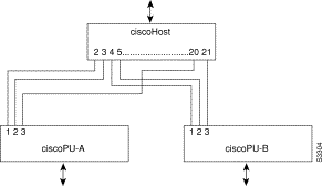
The following is a configuration file for the dedicated LU routing shown in Figure 30-3:
dspu host ciscohost xid-snd 06500001 rmac 4000.3745.0001
dspu pu ciscopu-a xid-rcv 05D00001 rmac 1000.5AED.0001
dspu lu 1 2 host ciscohost 2
dspu lu 3 3 host ciscohost 20
dspu pu ciscopu-b xid-rcv 05D00002 rmac 1000.5AED.0002
dspu lu 1 2 host ciscohost 4
dspu lu 3 3 host ciscohost 21
Figure 30-4 illustrates the use of pooled LU routing. Each upstream LU is configured in the LU pool and each downstream LU is configured as a pooled LU.
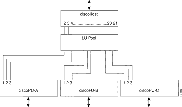
The following is the configuration example for the pooled LU routing shown in Figure 30-4:
dspu host ciscohost xid-snd 06500001 rmac 4000.3745.0001
dspu pool lupool host ciscohost lu 2 21
dspu pu ciscopu-a xid-rcv 05D00001 rmac 1000.5AED.0001
dspu lu 1 3 pool lupool
dspu pu ciscopu-b xid-rcv 05D00002 rmac 1000.5AED.0002
dspu lu 1 3 pool lupool
dspu pu ciscopu-c xid-rcv 05D00003 rmac 1000.5AED.0003
dspu lu 1 3 pool lupool
The following configuration example represents one possible definition for the network topology shown earlier in Figure 30-1.
This example demonstrates the configuration of an upstream host via RSRB (with local-acknowledgment) and downstream PUs via Token Ring.
source-bridge ring-group 99
source-bridge remote-peer 99 tcp 150.10.13.1
source-bridge remote-peer 99 tcp 150.10.13.2 local-ack
dspu rsrb 88 1 99 4000.ffff.0001
dspu rsrb enable-host lsap 4
dspu host ciscohost xid-snd 06500001 rmac 4000.3172.0001 rsap 4 lsap 4
dspu pool ciscopool host ciscohost lu 2 8
dspu rsrb start ciscohost
dspu pu ciscopu1 xid-rcv 05d00001
dspu lu 2 3 pool ciscopool
dspu pu ciscopu2 xid-rcv 05d00002
dspu lu 2 4 pool ciscopool
dspu pu ciscopu3 xid-rcv 05d00003
dspu lu 2 2 pool ciscopool
dspu pu ciscopu4 xid-rcv 05d00004
dspu lu 2 2 pool ciscopool
dspu lu 3 3 host ciscohost 9
interface TokenRing 0
description TokenRing connection for downstream PUs
ring-speed 16
dspu enable-pu lsap 8
This example demonstrates the configuration of downstream PUs via SDLC and an upstream host via Token Ring.
dspu host ciscohost xid-snd 06500001 rmac 4000.3172.0001 rsap 4 lsap 12
dspu pool ciscopool host ciscohost lu 2 11
dspu pu pu-sdlc0 sdlc C1 interface Serial0
dspu lu 2 6 pool ciscopool
dspu pu pu-sdlc1 sdlc C1 interface Serial1
dspu lu 2 6 pool ciscopool
interface Serial0
description SDLC connection for pu-sdlc0
encapsulation sdlc
sdlc role primary
sdlc address C1
dspu enable-pu sdlc C1
clockrate 56000
interface Serial1
description SDLC connection for pu-sdlc1
encapsulation sdlc
sdlc role primary
sdlc address C1
dspu enable-pu sdlc C1
clockrate 56000
interface TokenRing 0
description TokenRing connection for ciscohost
ring-speed 16
dspu enable-host lsap 12
dspu start ciscohost
This example demonstrates the configuration of an upstream host via SDLC and downstream PUs via Token Ring and Ethernet.
dspu host ciscohost xid-snd 06500001 sdlc C1 interface Serial0
dspu pool ciscopool host ciscohost lu 2 11
dspu pu pu-token rmac 4000.4444.0001 rsap 4 lsap 8
dspu lu 2 6 pool ciscopool
dspu pu pu-ether rmac 0200.2222.0001 rsap 4 lsap 8
dspu lu 2 6 pool ciscopool
interface Serial0
description SDLC connection for ciscohost
encapsulation sdlc
sdlc role secondary
sdlc address C1
dspu enable-host sdlc C1
clockrate 56000
interface TokenRing 0
description TokenRing connection for pu-token
ring-speed 16
dspu enable-pu lsap 8
interface Ethernet0
description Ethernet connection for pu-ether
dspu enable-pu lsap 8
This example demonstrates the configuration of a downstream PU via QLLC/X.25 and upstream host via Ethernet.
x25 routing
dspu host ciscohost xid-snd 06500001 rmac 0200.2222.0001 rsap 4 lsap 12
dspu pool ciscopool host ciscohost lu 2 11
dspu pu pu-qllc x25 320108 qllc 08
dspu lu 2 11 pool ciscopool
interface Serial0
description QLLC connection for pu-qllc
encapsulation x25
x25 address 3202
x25 map qllc 320108
dspu enable-pu qllc 8
interface Ethernet0
description Ethernet connection for pu-ether
dspu enable-host lsap 12
dspu start ciscohost
x25 route ^3202.* alias Serial0
This example demonstrates the configuration of an upstream host via Frame Relay and downstream PUs via Token Ring and Ethernet.
dspu host ciscohost xid-snd 06500001 dlci 200 rsap 4 lsap 12
dspu pool ciscopool host ciscohost lu 2 11
dspu pu pu-token rmac 4000.4444.0001 rsap 4 lsap 8
dspu lu 2 6 pool ciscopool
dspu pu pu-ether rmac 0200.2222.0001 rsap 4 lsap 8
dspu lu 2 6 pool ciscopool
interface Serial0
description Frame Relay connection for ciscohost
encapsulation frame-relay ietf
frame-relay map llc2 200
dspu enable-host lsap 12
dspu start ciscohost
interface TokenRing 0
description TokenRing connection for pu-token
ring-speed 16
dspu enable-pu lsap 8
interface Ethernet0
description Ethernet connection for pu-ether
dspu enable-pu lsap 8
The following is an example of an RSRB configuration that implements SNA Service Point:
source-bridge ring-group 99
source-bridge remote-peer 99 tcp 150.10.13.2 local-ack
sna rsrb 88 1 99 4000.ffff.0001
sna host CNM02 xid-snd 05dbc000 rmac 4001.3745.1088 rsap 4 lsap 4 focalpoint
sna rsrb enable-host lsap 4
sna rsrb start CNM02
|
|