|
|

This chapter describes our Frame Relay access support for System Network Architecture (SNA) devices. For a complete description of the commands mentioned in this chapter, refer to the "SNA Frame Relay Access Support Commands" chapter of the Router Products Command Reference publication.
Because Frame Relay offers cost-effective means of transporting multiple protocols on a wide-area network (WAN), IBM now supports Frame Relay multiprotocol encapsulation functions on a wide range of IBM devices.
Management Service Point Support in FRAS allows the de facto SNA Network Management application NetView to manage Cisco Routers over the Frame Relay network as if it were an SNA downstream PU.
FRAS provides Dial Backup over RSRB in case the Frame Relay network is down. While the backup public switched telephone network (PSTN) is being used, the Frame Relay connection is tried periodically. As soon as the Frame Relay network is up, it will be used at once.
The multiprotocol encapsulation specification is described in RFC 1490 and FRF.3 Agreement from the Frame Relay Forum (FRF).
RFC 1490 specifies a standard method of encapsulating multiprotocol traffic with data link (Level 2 of the OSI model) framing.The encapsulation for SNA data is specified in the FRF.3 Agreement.
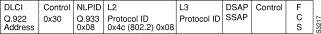
The Frame Relay encapsulation method is based on the RFC 1490 frame format for "user-defined" protocols using Q.933 NLPID, as illustrated in Figure 31-1.
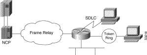
Our Frame Relay Access support consists of a router acting as a Frame Relay Access Device (FRAD) for Synchronous Data Link Control (SDLC), Token Ring, and Ethernet attached devices over a Frame Relay Boundary Network Node (BNN) link. Frame Relay access support allows the router acting as a FRAD to take advantage of the SNA BNN support for Frame Relay provided by ACF/NCP 7.1 and OS/400 V2R3. Downstream PU 2.0 and PU 2.1 devices can be attached to the router through SDLC, Token Ring or Ethernet links. The router acting as a FRAD is connected to the NCP or AS/400 through a public or private Frame Relay network, as illustrated in Figure 31-2.
The frame format used to communicate across the Frame Relay BNN link is defined in RFC 1490 for routed SNA traffic. From the perspective of the SNA host (for example an NCP or AS/400), the Frame Relay connection is defined as a switched resource similar to a Token Ring BNN link.
The router is responsible for terminating the local data link control (DLC) frames (such as SDLC and Token Ring frames) and for modifying the DLCs to 802.2 compliant LLC frames. The LLC logical link is used to provide a reliable connection-oriented link layer transport required by SNA. (For example, 802.2 LLC is used to provide link layer acknowledgment, sequencing and flow control.)
The router encapsulates these 802.2 LLC frames according to the RFC 1490 format for SNA traffic. The frames are then forwarded to the SNA host on a Frame Relay permanent virtual circuit (PVC). In the reverse direction, the router is responsible for de-encapsulating the data from the Frame Relay PVC, and for generating and transmitting the appropriate local DLC frames to the downstream devices.
To configure Frame Relay access support, perform the tasks described in the following sections:
See the end of this chapter for "Frame Relay Access Support Configuration Examples."
To configure Frame Relay access support, perform one of the following tasks in interface configuration mode:
Since Frame Relay itself does not provide a reliable transport as required by SNA, the RFC 1490 support of SNA uses LLC2 as part of the encapsulation to provide link-level sequencing, acknowledgment and flow control. The serial interface configured for Internet Engineering Task Force (IETF) encapsulation (in other words, RFC 1490) can take all LLC2 interface configuration commands.
Frame Relay access support provides a congestion control mechanism based on the interaction between congestion notification bits in the Frame Relay packet and the dynamic adjustment of the LLC2 send window. This window is the number of frames the router can send before waiting for an acknowledgment. The window size decreases with the occurrence of backward explicit congestion notification (BECN), and increases when no BECN frames are received.
To configure congestion management, perform the following tasks in interface configuration mode:
| Task | Command |
|---|---|
| Specify the maximum window size for each logical connection. | llc2 local-window size1 |
| Enable the dynamic window flow-control mechanism. | llc2 dynwind [nw nw-number] [dwc dwc-number] |
You can enable the dynamic window mechanism only if you are using Frame Relay IETF encapsulation.
When the Frame Relay network is down, the router software checks whether the dial backup feature is configured for the particular DLCI number. If it is configured, the software removes the FRAS to the downstream device connection and establishes the RSRB to this downstream device connection.
To configure RSRB dial backup, perform the following task in interface configuration mode:
| Task | Command |
|---|---|
| Activate Frame Relay RSRB dial backup. | fras backup rsrb vmacaddr local-ring-number target-ring-number host-mac-address |
To display information about the state of Frame Relay access support, perform the following command in privileged EXEC mode:
| Task | Command |
|---|---|
| Display the mapping and connection state of the Frame Relay access support. | show fras map |
The following sections provide Frame Relay access support configuration examples:
Figure 31-3 illustrates the configuration of SNA devices attached to a local-area network (LAN).
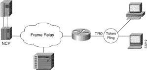
The following is the configuration for the network shown in Figure 31-3:
interface TokenRing 0
no ip address
no keepalive
ring-speed 16
fras map llc 0800.5a8f.8802 4 4 serial 0 frame-relay 200 4 4
!
interface serial 0
mtu 2500
no ip address
encapsulation frame-relay IETF
keepalive 12
frame-relay lmi-type ansi
frame-relay map llc2 200
Figure 31-4 illustrates the configuration of SDLC-attached SNA devices.
The following is the configuration file for the network shown in Figure 31-4:
interface serial 1
no ip address
encapsulation sdlc
no keepalive
clockrate 56000
sdlc address C1
sdlc xid C1 05D01501
sdlc role primary
fras map sdlc C1 serial 0 frame-relay 200 4 4
!
interface serial 0
mtu 2500
no ip address
encapsulation frame-relay IETF
keepalive 12
frame-relay lmi-type ansi
frame-relay map llc2 200
|
|