|
|

Product Number RSP7000CI=
This document contains instructions for replacing the 7000 Series Chassis Interface (RSP7000CI) in the Cisco 7000 series routers: the Cisco 7000 and Cisco 7010. The RSP7000CI provides all of the environmental monitoring functions for the Cisco 7000 series router and is a required system component in a Cisco 7000 series chassis configured with the RSP7000.
In the Cisco 7000, the RSP7000CI is installed in the 7000 CI slot (slot 6 in the Cisco 7000 and slot 4 in the Cisco 7010) on the interface processor end of the Cisco 7000 series chassis.
The RSP7000CI operation requires that your Cisco 7000 series router has an RSP7000 installed, and is running Cisco Internetwork Operating System (Cisco IOS) Release 10.3(9), or later, Release 11.0(6), or later, or Release 11.1(1) or later.
The sections in this document include the following:
Following are brief descriptions of the Cisco 7000 series routers and the RSP7000CI.
The Cisco 7000 is a seven-slot router chassis, which uses the new RSP7000 kit. The Cisco 7000 provides up to five interface processor slots, and can accommodate the following CxBus-based interface processors: Fast Ethernet, Ethernet, Token Ring, Fiber Distributed Data Interface (FDDI), channel attachment, multichannel, serial, and so forth. The RSP7000, RSP7000CI, and interface processors are keyed with guides on the backplane to prevent them from being fully inserted in the wrong slot.
Figure 1 shows the rear of the Cisco 7000 router. In the Cisco 7000, slot 6 is reserved for the RSP7000CI board, which contains all of the environmental monitoring functions for the Cisco 7000, when configured with the new 7000 RSP. The remaining six slots (0 through 5) are for interface processors and the RSP7000.
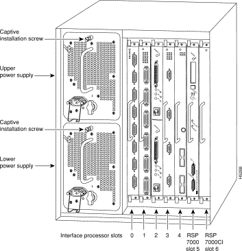
The Cisco 7010 is a five-slot chassis, which uses the new RSP7000CI (and the RSP7000), and provides up to three interface processor slots that can accommodate the following CxBus-based interface processors: Fast Ethernet, Ethernet, Token Ring, Fiber Distributed Data Interface (FDDI), channel attachment, multichannel, serial, and so forth. The processor and interface processors are keyed with guides on the backplane to prevent them from being fully inserted in the wrong slot.
Figure 2 shows the rear of the Cisco 7010 router with the RSP7000CI and RSP7000 installed. In the Cisco 7010, slot 4 is reserved for the RSP7000CI, which contains all of the environmental monitoring functions for the Cisco 7010. The remaining three slots (slots 0 through 2) are for interface processors.
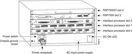
The RSP7000CI, shown in Figure 3 on page 4, consists of a printed circuit board attached to a metal carrier. The RSP7000CI provides the environmental monitoring and power supply monitoring functions for the Cisco 7000 series chassis. The RSP7000CI isolates the CPU and system software from chassis-specific variations. The RSP7000CI has no user-configurable jumpers or switches, and its faceplates contains no LEDs. The RSP7000CI is distinguishable only by the label on its faceplate, which reads 7000 Chassis Interface.
You must install the RSP7000CI in the appropriate chassis' 7000 CI slot. (See Figure 1 on page 2, for the Cisco 7000, or Figure 2 on page 3 for the Cisco 7010.) For the appropriate Cisco IOS version required for the RSP7000CI, refer to the section "Preventing Electrostatic Discharge Damage".
The functions of the RSP7000CI are as follows:

 | Caution To prevent system problems, the RSP7000CI must not be removed with power on to the chassis. The RSP7000CI does not support online insertion and removal (OIR). |
Before you begin this installation, review the safety guidelines in this section to avoid injuring yourself or damaging the equipment.
Following are safety guidelines that you should follow when working with any equipment that connects to electrical power or telephone wiring.
Follow these basic guidelines when working with any electrical equipment:
Electrostatic discharge (ESD) damage, which can occur when electronic cards or components are improperly handled, results in complete or intermittent failures. Electromagnetic interference (EMI) shielding and connectors are integral components of the carrier. Use a preventive antistatic strap whenever handling a processor module.
Following are guidelines for preventing ESD damage:
 | Caution For safety, periodically check the resistance value of the antistatic strap. The measurement should be between 1 and 10 megohms. |
The RSP7000CI is compatible with any Cisco 7000 series routers that is operating with the following software and hardware:
The show version command displays the current hardware configuration of the router, including the Cisco IOS release that is currently loaded and running. The show controllers cbus command lists all CxBus interfaces installed in the system.
 | Caution To prevent system problems, the RSP7000CI must not be removed with power ON to the chassis. The RSP7000CI does not support online insertion and removal (OIR). |
Following are the tools and equipment that you will need to complete this replacement:
Following are the replacement procedures for replacing an RSP7000CI in your Cisco 7000 series router. You must turn off all system power before replacing the RSP7000CI.
 | Caution To prevent system problems, the RSP7000CI must not be removed with power ON to the chassis. The RSP7000CI does not support online insertion and removal (OIR). |
Remove the existing RSP7000CI as follows:
Step 2 Locate the RSP7000CI, which is installed in the 7000 CI slot (slot 6 in a Cisco 7000 and slot 4 in a Cisco 7010. (See Figure 1 or Figure 2.)
Figure 4 shows the orientation of the RSP7000CI for the Cisco 7000.
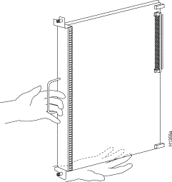
Figure 5 shows the orientation of the RSP7000CI for a Cisco 7010.
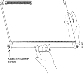
Step 3 Use a screwdriver (number 2 Phillips or 3/16-inch flat-blade) to loosen the two captive installation screws. (See Figure 6a.)
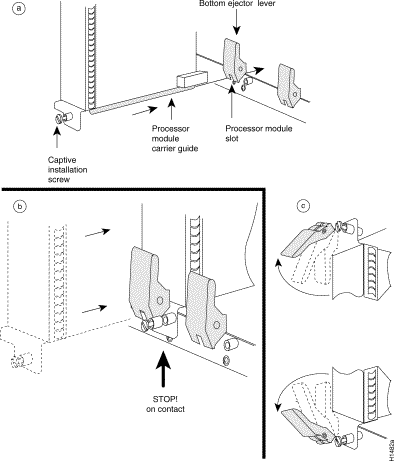
Step 4 Place your thumbs on the ends of each of the ejectors and simultaneously pull them both outward, away from the carrier handle (in the opposite direction from that shown in Figure 6c) to release the carrier from the slot and to dislodge the RSP7000CI from the backplane.
Step 5 Grasp the handle with one hand and pull the RSP7000CI straight out of the slot (see Figure 6b), keeping your other hand under the carrier to guide it.Keep the carrier parallel to the backplane. Avoid touching the board or any connector pins.
Step 6 Place the removed RSP7000CI on an antistatic mat or foam. If you plan to return the RSP7000CI to the factory, immediately place it in an antistatic bag to prevent ESD damage.
Proceed to the section "Installing the New RSP7000CI."
Ensure that all system power is turned off before installing the RSP7000CI in the chassis. The RSP7000CI is keyed for installation only in the RSP7000CI slot (slot 6). (See Figure 1 on page 2.)
Follow these steps to install an RSP7000CI:
Step 2 Grasp the RSP7000CI handle with one hand and place your other hand under the carrier to support and guide it into the slot. Avoid touching the board or any connectors.
Step 3 Place the back of the RSP7000CI in the 7000 CI slot (see Figure 1, on page 2, for the Cisco 7000 or Figure 2, on page 3, for the Cisco 7010) and align the notches along the edge of the carrier with the grooves in the slot. (See Figure 6a.)
 | Caution To prevent damage to the backplane, you must install the RSP7000CI in the 7000 CI slot of your Cisco 7000 series router. (See Figure 1 or Figure 2.) The slots are keyed for correct installation. Forcing the RSP7000CI into a different slot can damage the backplane and the RSP7000CI. |
Step 4 While keeping the RSP7000CI parallel to the backplane, carefully slide the carrier into the 7000 CI slot until the RSP7000CI faceplate makes contact with the ejector levers, then stop. (See Figure 6b.)
Step 5 Using the thumb and forefinger of each hand to pinch each ejector, simultaneously push both ejectors inward (toward the handle) until they parallel to the faceplate. (See Figure 6c.)
Step 6 Use a screwdriver (number 2 Phillips or 3/16-inch flat-blade) to tighten the captive installation screws on the ends of the RSP7000CI. (See Figure 6a.)
Tighten the two captive screws on the RSP7000CI faceplate to prevent the RSP7000CI from becoming partially dislodged from the backplane and to ensure proper EMI shielding. (These screws must be tightened to meet EMI specifications.)
Step 7 Ensure that the console terminal is connected to the console port on the RSP7000, and that the terminal is turned on.
Step 8 Turn the system power back ON, and proceed to the next section to check the installation.
Verify RSP700CI is installed in the chassis' 7000 CI slot (see Figure 1 on page 2 or Figure 2 on page 3), and that both of the captive installation screws are tightened.
Using the RSP7000CI and the temperature sensors on the RSP7000, the system displays warning messages on the console if chassis interface-monitored parameters exceed a desired threshold or if a blower failure occurs. You can retrieve and display environmental status reports with the show environment, show environment all, show environment last and show environment table commands. Parameters are measured and reporting functions are updated every 60 seconds. A brief description of each of these commands follows.
Use these show commands to indicate that the RSP7000CI installation was successful.
The show environment command display reports the current environmental status of the system. The report displays parameters that are out of the normal values. No parameters are displayed if the system status is normal. The example that follows shows the display for a system in which all monitored parameters are within Normal range.
Following is sample output of the show env command:
Router# show env


All measured values are normal
If the environmental status is not normal, the system reports the worst-case status level in the last line of the display.
RSP7000#sho env last

  CI(6) Inlet        previously measured at 22C/71F
    CI(6) Hotpoint     previously measured at 31C/87F
      CI(6) Exhaust      previously measured at 23C/73F
        +12 Voltage        previously measured at 12.12
          +5 Voltage         previously measured at 5.13
            -12 Voltage        previously measured at -11.84
              +24 Voltage        previously measured at 24.06

RSP7010#sho env last

  CI(4) Inlet        previously measured at 23C/73F
  CI(4) Hotpoint     previously measured at 35C/95F
  CI(4) Exhaust      previously measured at 25C/77F
  +12 Voltage        previously measured at 12.31
  +5 Voltage         previously measured at 5.17
  -12 Voltage        previously measured at -11.89
  +24 Voltage        previously measured at 23.78
The show environment table command displays the temperature and voltage thresholds for each of the three RSP7000 temperature sensors, for each monitored status level: low critical, low warning, high warning, and high critical. The slots in which the RSP7000 can be installed are indicated in parentheses (2 and 3). Also listed are the shutdown thresholds for the processor boards and power supplies. An example of the show env table command follows for both the Cisco 7000 and Cisco 7010:
RSP7000#sho env table

Sample Point      LowCritical    LowWarning     HighWarning
HighCritical
CI(6) Inlet                       44C/111F       50C/122F
CI(6) Hotpoint                    54C/129F       60C/140F
CI(6) Exhaust
+12 Voltage       10.90          11.61          12.82          13.38
+5 Voltage        4.61           4.94           5.46           5.70
-12 Voltage       -10.15         -10.76         -13.25         -13.86
+24 Voltage       20.38          21.51          26.42          27.65
2.5 Reference                    2.43           2.51
Shutdown power supplies at   70C/158F

RSP7010#sho env table

Sample Point      LowCritical    LowWarning     HighWarning
HighCritical
CI(4) Inlet                                     44C/111F       50C/122F
CI(4) Hotpoint                                  54C/129F       60C/140F
CI(4) Exhaust
+12 Voltage       10.90          11.61          12.82          13.38
+5 Voltage        4.61           4.94           5.46           5.70
-12 Voltage       -10.15         -10.76         -13.25         -13.86
+24 Voltage       20.38          21.51          26.42          27.65
2.5 Reference                    2.43           2.51
Shutdown power supplies at   70C/158F
The show environment all command displays an extended report that includes the arbiter type, backplane type, power supply type (AC or DC), wattage and status, the number and type of intermittent power failures (if any) since the system was last powered on, and the currently measured values at the RSP7000 temperature sensors and the power supply voltages. An example of the show env all command follows for both the Cisco 7000 and Cisco 7010:
RSP7000#sho env all

 Arbiter type 1, backplane type 70x0 (id 5)
 Power supply #1 is 700W (id 2), power supply #2 is removed (id 3)
 Active fault conditions: none
 Active trip points: none

                         0123456
             Dbus slots:  X   X

              card     inlet       hotpoint     exhaust
               CI(6)   21C/69F      30C/86F      22C/71F

               Shutdown temperature source is 'hotpoint' on CI(6),
               requested CI(6)

               +12V measured at 12.12
                +5V measured at 5.13
                -12V measured at -11.84
                +24V measured at 24.06
                +2.5 reference is 2.49
RSP7010#sho env all

 Arbiter type 1, backplane type 70x0 (id 5)
 Power supply #1 is 600W AC (id 1)
 Active fault conditions: none
 Active trip points: none

                         01234
             Dbus slots:  X X

              card     inlet       hotpoint     exhaust
               CI(4)   22C/71F      34C/93F      24C/75F

               Shutdown temperature source is 'hotpoint' on CI(4),
               requested CI(4)

               +12V measured at 12.31
                +5V measured at 5.17
                -12V measured at -11.89
                +24V measured at 23.78
                +2.5 reference is 2.49
If after several attempts, the RSP7000CI does not appear to be functioning properly, or if you experience trouble with the installation (for instance, if the holes in the board do not align with the backplane holes), contact a service representative or the Technical Assistance Center (TAC). (For the TAC phone number and email address, refer to the note at the end of this document.
This completes the RSP7000CI replacement in the Cisco 7000 series router.
Cisco Information Online (CIO), formerly Cisco Information Online (CIO), is Cisco Systems' primary, real-time support channel. Maintenance customers and partners can self-register on CIO to obtain additional content and services.
Available 24 hours a day, 7 days a week, CIO provides a wealth of standard and value-added services to Cisco's customers and business partners. CIO services include product information, software updates, release notes, technical tips, the Bug Navigator, configuration notes, brochures, descriptions of service offerings, and download access to public and authorized files.
CIO serves a wide variety of users through two interfaces that are updated and enhanced simultaneously—a character-based version and a multimedia version that resides on the World Wide Web (WWW). The character-based CIO (called "CIO Classic") supports Zmodem, Kermit, Xmodem, FTP, Internet e-mail, and fax download options, and is excellent for quick access to information over lower bandwidths. The WWW version of CIO provides richly formatted documents with photographs, figures, graphics, and video, as well as hyperlinks to related information.
You can access CIO in the following ways:
http://www.cisco.com
cio.cisco.com
For a copy of CIO's Frequently Asked Questions (FAQ), contact cio-help@cisco.com. For additional information, contact cio-team@cisco.com.
tac@cisco.com. To obtain general information about Cisco Systems, Cisco products, or upgrades, contact 800 553-6387, 408 526-7208, or cs-rep@cisco.com.
![]()
![]()
![]()
![]()
![]()
![]()
![]()
![]()
Posted: Tue Mar 27 14:46:46 PST 2001
All contents are Copyright © 1992--2001 Cisco Systems, Inc. All rights reserved.
Important Notices and Privacy Statement.